
 100% FREE ACCESS
12th Standard CBSE Syllabus & Materials
12th Standard CBSE
CBSE 12th Economics Government Budget and the Economy Previous year Question Papers Study Material - QB365 Set A
NEW12th Standard CBSE
CBSE 12th Computer Science Interface Python with MySQL - New Previous year Question Papers Study Material - QB365 Set A
NEW12th Standard CBSE
CBSE 12th Computer Science Database Concept - New Previous year Question Papers Study Material - QB365 Set A
NEW12th Standard CBSE
CBSE 12th Computer Science Data Communication - New Previous year Question Papers Study Material - QB365 Set A
NEW12th Standard CBSE
CBSE 12th Computer Science Data Structures - New Previous year Question Papers Study Material - QB365 Set A
NEW12th Standard CBSE
CBSE 12th Computer Science Functions - New Previous year Question Papers Study Material - QB365 Set A

Published on: 07/03/2026
Download CBSE Class 12th Standard CBSE Physics question papers, sample papers, important questions, and previous year solved papers in PDF format. Get free study materials, NCERT solutions, and exam preparation resources for Class 12th Standard CBSE Physics
Questions + Answers key
Take MCQ Physics Test
1.
The given figure shows a small magnetised needle P placed at a point O. The arrow shows the direction of its magnetic moment. The other arrows show different positions (and orientations of the magnetic moment) of another identical magentised needle B.

(a) In which configuration the system is not in equilibrium?
(b) In which configuration is the system in (i) stable, and (ii) unstable equilibrium?
(c) Which configuration corresponds to the lowest potential energy among all the configurations shown?
2.
(a) Define the current sensitivity of a galvanometer. Write its SI unit.
(b) Figure shows two circuits each having a galvanometer and a battery of 3 V.
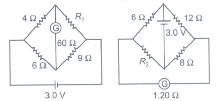
When the galvanometers in each arrangement do not show any deflection, obtain the ratio R1/R2.
3.
Find the value of the phase difference between the current and the voltage in the series L-C-R circuit shown below. Which one leads in phase: current or voltage?
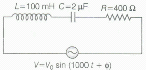
Without making any other change, find the value of the additional capacitor C', to be connected in parallel with the capacitor C, in order to make the power factor of the circuit unity.
4.
In a series L-C-R circuit connected to an AC source of variable frequency and voltage \(V\ =\ { V }_{ m }\ sin\ \omega t\), draw a plot showing the variation of current I with angular frequency \(\omega \), for two different values of resistance R1and R2(R1>R2). Write the condition under which the phenomenon of resistance occurs. For which value of the resistance out of the two curves, a sharper resonance is produced? Define Q-factor of the circuit and give its significance.
5.
An a.c. generator consists of a coil of 100 turns and cross sectional area of \(3{ m }^{ 2 }\), rotating at a constant angular speed of 60 rad/sec in a uniform magnetic field of 0.04 T. The resistance of the coil is \(500 \ \Omega \). Calculate
(i) maximum current drawn from the generator and
(ii) max. power dissipation in the coil.
6.
An alpha particle moves along a circular path of radius 2Ao with a uniform speed of 2x10⁶ ms-1 . Calculate the magnetic field set up at the centre of circular path.
7.
A coil of 200 turns has a cross-sectional area 900mm2 It carries a current of 2 ampere. The plane of the coil is perpendicular to a uniform magnetic field of 0.5T. Calculate (i) the magnetic moment of the coil and (ii) the torque acting on the coil.
8.
What is the radius of the path of an electron (mass 9 x 10-31 kg and charge 1.6 x 10⁻¹⁹ C) moving at a speed of 3 x 10⁷ m/s in a magnetic field of 6 x 10⁻⁴ T perpendicular to it? What is its frequency? Calculate its energy in keV. ( 1 eV = 1.6 x 10⁻¹⁹ J).
9.
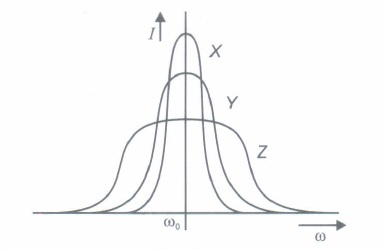
Three students X, Y, and Z performed an experiment for studying the variation of alternating current with angular frequency in a series LCR circuit and obtained the graphs as shown. They all used a.c sources of the same r.m.s. value and inductances of the same value. What can we (qualitatively) conclude about the
(i) capacitance value
(ii) resistance values Used by them? In which case will the quality factor be maximum? What can we conclude about nature of the impedance of the setup at frequency wo?
10.
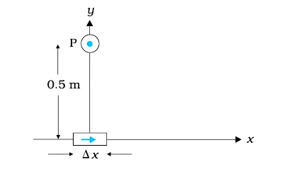
An element Δl = Δx \(\hat i\) is placed at the origin and carries a large current I = 10 A (Figure). What is the magnetic field on the y-axis at a distance of 0.5 m. Δ x = 1 cm.
11.
Classify the following into dia and para magnetic substances : aluminium, copper, water, mercury, oxygen,hydrogen.
12.
What is the average value of alternating current,\(I={ I }_{ 0 }sin\ \omega t\) over time interval \(t=\pi /\omega \ to\ t=2\pi /\omega \)
13.
What is the magnitude and direction of force on an electron moving along the direction of the magnetic field.
14.
Compare Gauss's law and ampere's law.
15.
A galvanometer coil has a resistance of 12 Ω and the metre shows full scale deflection for a current of 3 mA. How will you convert the metre into a voltmeter of range 0 to 18 V ?
16.
Two moving coil meters, M1 and M2 have the following particulars:
R1 = 10 Ω, N1 = 30, A1 = 3.6 x 10⁻³ m2, B1 = 0.25 T
R2 = 14 Ω, N2 = 42, A2 = 1.8 x 10⁻³ m2, B2 = 0.50 T
(The spring constants are identical for the two meters). Determine the ratio of (a) current sensitivity and (b) voltage sensitivity of M2 and M1.
17.
A solenoid of 600 turns per metre is carrying a current of 4 A. Its core is made of iron with relative permeability of 5000. Calculate the magnitudes of magnetic intensity, intensity of magnetisation and magnetic field inside the core.
18.
Derive an expression for the impedance of a series LCR circuit connected to an AC supply of variable frequency.
Plot a graph showing variation of current with the frequency of the applied voltage. Explain briefly how the phenomenon of resonance in the circuit can be used in the tuning mechanism of a radio or a TV set.
19.
Derive an expression for average power in an A.C. circuit containing resistor only.
20.
The relative permeability of a substance X is slightly less than unity and that of substance Y is slightly more than unity, then
X is paramagnetic and Y is ferromagnetic
X is diamagnetic and Y is ferromagnetic
X and Y both are paramagnetic
X is diamagnetic and Y is paramagnetic
21.
In an ammeter 0.5% of main current passes through galvanometer. If resistance of galvanometer is G, the resistance of ammeter will be
G/200
G/199
199 G
200G.
22.
A charged particle goes undeflected in a region containing electric and magnetic field. It is possible that
\(\vec { E } \parallel \vec { B } \) but \(\vec { \upsilon } \) is not parallel to \(\vec { E } \)
\(\vec { \upsilon } \parallel \vec { B } \) but \(\vec { E } \) is not parallel to \(\vec { B } \)
\(\vec { E } \parallel \vec { B } \), \(\vec { \upsilon } \parallel \vec { E } \)
\(\vec { E } \) is not parallel to \(\vec { B } \) and \(\vec { \upsilon } \)
23.
Tthe line that draws power supply to your house from street has
zero average current
220V average voltage
voltage and current out of phase by \({ 90 }^{ \circ }\)
voltage and current possibly differing in phase \(\phi \) such that \(\left| \phi \right| <\frac { \pi }{ 2 } \)
24.
A battery of 12V is connected to primary of a transformer with turns ratio ns/np= 10. Voltage across secondary would by
120 V
1.3 V
12 V
Zero
25.
A circular coil of n turns and radius r carries a current I. The magnetic field at the centre is
\(\frac { { \mu }_{ o }nI }{ r } \)
\(\frac { { \mu }_{ o }nI }{ 2r } \)
\(\frac { { 2\mu }_{ o }nI }{ r } \)
\(\frac { { \mu }_{ o }nI }{ 4r } \)
26.
A positive charge is moving towards an observer. The direction of magnetic induction lines is
clockwise
anticlockwise
right
left
27.
Q factor of resonance is given by
\(\frac { 1 }{ R } \sqrt { \frac { L }{ C } } \)
\(\frac { 1 }{ R } \sqrt { \frac { C }{ L } } \)
\(\frac { 1 }{ L } \sqrt { \frac { R }{ C } } \)
\(\frac { 1 }{ C } \sqrt { \frac { L }{ R } } \)
28.
The power averaged over one full cycle of a.c. is known as average power. It is also known as true power
\(P_{\mathrm{av}}=V_{\mathrm{rms}} I_{\mathrm{rms}} \cos \phi=\frac{V_{0} I_{0}}{2} \cos \phi\)
Root mean square or simply rms watts refer to continuous power
A circuit containing a 80.mH inductor and a \(60 \mu \mathrm{F}\) capacitor in series is connected to a 230 V, 50 Hz supply. The resistance of the circuit is negligible.
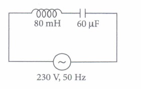
(i) The value of current amplitude is
| (a) 15 A | (b) 11.63 A | (c) 17.65 A | (d) 6.33 A |
(ii) Find rms value.
| (a) 6 A | (b) 5.25 A | (c) 8.23 A | (d) 7.52A |
(iii) The average power transferred to inductor is
| (a) zero | (b) 7W | (c) 2.5 W | (d) 5 W |
(iv) The average power transferred to the capacitor is
| (a) 5 W | (b) zero | (c) 11 W | (d) 15 W |
(v) What is the total average power absorbed by the circuit?
| (a) zero | (b) 10W | (c) 2.5 W | (d) 15W |
29.
A galvanometer can be converted into voltmeter of given range by connecting a suitable resistance Rs in series with the galvanometer, whose value is given by
\(R_{s}=\frac{V}{I_{g}}-G\)
where V is the voltage to be measured, Ig is the current for full scale deflection of galvanometer and G is the resistance of galvanometer
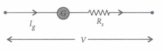
Series resistort (Rs) increases range of voltmeter and the effective resistance of galvanometer. It also protects the galvanometer from damage due to large current.
Voltmeter is a high resistance instrument and it is always connected in parallel with the circuit element across which potential difference is to be measured. An ideal voltmeter has infinite resistance
In order to increase the range of voltmeter n times the value of resistance to be connected in series with galvanometer is Rs = (n - l)G.
(I) 10 mA current can pass through a galvanometer of resistance \(25 \Omega\) What resistance in series should be connected through it, so that it is converted into a voltmeter of 100 V?
| \(\text { (a) } 0.975 \Omega\) | \(\text { (b) } 99.75 \Omega\) | \(\text { (c) } 975 \Omega\) | \(\text { (d) } 9975 \Omega \text { . }\) |
(ii) There are 3 voltmeter A, B, C having the same range but their resistance are \(15,000 \Omega, 10,000 \Omega\) and \(5,000 \Omega\) respectively. The best voltmeter amongst them is the one whose resistance is
| \(\text { (a) } 5000 \Omega\) | \(\text { (b) } 10,000 \Omega\) | \(\text { (c) } 15,000 \Omega\) | (d) all are equally good |
(iii) A milliammeter of range 0 to 25 mA and resistance of \(10 \Omega\) is to be converted into a voltmeter with a range of 0 to 25 V. The resistance that should be connected in series will be
| (a) \(930 \Omega\) | \(\text { (b) } 960 \Omega\) | \(\text { (c) } 990 \Omega\) | \(\text { (d) } 1010 \Omega\) |
(iv) To convert a moving coil galvanometer (MCG) into a voltmeter
| (a) a high resistance R is connected in parallel with MCG |
| (b) a low resistance R is connected in parallel with MCG |
| (c) a low resistance R is connected in series with MCG |
| (d) a high resistance R is connected in series with MCG |
(v) The resistance of an ideal voltmeter is
| (a) zero | (b) low | (c) high | (d) infinity |
30.
31.
Assertion : The energy of a charged particle moving in a uniform magnetic field remains constant.
Reason : Work done by the magnetic field on the charge is zero.
Codes:
A) Both A and R are true and R is the correct explanation of A
B) Both A and R are true but R is NOT the correct explanation of A
C) A is true but R is false
D) A is false and R is true
32.
Assertion (A) : Long distance transmission of A.C is carried out at extremely high voltage.
Reason (R) : For large distance, voltage has to be large.
Codes:
(a) Both A and R are true and R is the correct explanation of A
(b) Both A and R are true but R is NOT the correct explanation of A
(c) A is true but R is false
(d) A is false and R is also false
33.
Assertion (A) : The magnetic field intensity at the centre of a circular coil carrying current changes, if the current through the coil is doubled.
Reason (R) : The magnetic field intensity is dependent on current in conductor.
Codes:
(a) Both A and R are true and R is the correct explanation of A
(b) Both A and R are true but R is NOT the correct explanation of A
(c) A is true but R is false
(d) A is false and R is also false
1.
Potential energy of the configuration arises due to potential energy of one dipole (say B), in the magnetic field due to the other (A). Use the result that.
\(B_{A}=\frac{\mu_{0} M_{A}}{4 \pi r^{3}}\) (on the normal bisector)
\(B_{A}=\frac{\mu_{0} 2 M_{A}}{4 \pi r^{3}}\) (on the axis)
Equilibrium is stable when MB is parallel to BA and unstable when MB is anti-parallel to BA.
(a) AB1 and AB2
(b) (i) AB3, AB6 (stable), (ii) AB5, AB4 (unstable)
(c) AB6 (Maximum negative)
2.
(a) Current sensitivity of a galvanometer is defined as the deflection produced in the galvanometer when a unit current flows through it.
∴ Current sensitivity, \(I_{s}=\frac{\theta}{I}=\frac{N B A}{k}\)
Its SI unit is radian/ampere.
(b) For a balanced wheatstone bridge, there will be no deflection in the galvanometer.
Hence, for the first given figure
\(\frac{4}{R_{1}}=\frac{6}{9} \Rightarrow R_{1}=6 \Omega\)
If the bridge is balanced, then on interchanging the position of the galvanometer and the battery, there is no effect on the balance of the bridge. Hence for the 2nd given figure,
\(
\frac{6}{12}=\frac{R_{2}}{8}
\)
\(\Rightarrow \ R_{2}=4 \Omega
\)
Therefore, the required ratio is calculated as
\(\frac{R_{1}}{R_{2}}=\frac{6}{4}=\frac{3}{2}=3: 2\)
3.
Given, L = 100 mH = 100 x 10-3 H,
C = 2\(\mu\)F = 2 x 10⁻⁶ F, \(\omega\) = 1000 and R = 400 \(\Omega\)
For phase difference,
tan \(\phi={{\left( \omega L-{{1}\over{\omega C}} \right)}\over{R}}\)
[where, \(\phi\) is phase difference between current and voltage]
\(\therefore\) \(\omega\) = 1000 \(\Rightarrow\) \(\omega\)L = 1000 x 100 x 10-3 = 100 \(\Omega\)
\({{1}\over{\omega C}}={{1}\over{1000\times2\times{10}^{-6}}}={{1}\over{2\times{10}^{-3}}}=500\Omega\)
\(\Rightarrow\) \(tan\ \phi={{100-500}\over{400}}={{-400}\over{400}}=-1\)
\(\Rightarrow\) \(\phi\ ={tan}^{-1}(-1)\Rightarrow\ \phi=135°\)
Since, \(\omega L< {{1}\over{\omega C}}\) or XL < XC
Therefore, current is leading in phase by a phase angle 135°.
For unit power factor cos \(\phi\) = 1
\(\Rightarrow{{R}\over{\sqrt{{R}^{2}+\left(\omega L-{{1}\over{\omega C'}} \right)}}}=1\)
where C' is the total capacitance.
\(\Rightarrow\) \({R}^{2}+\left( \omega L-{{1}\over{\omega C'}} \right)^{2}={R}^{2}\)
\(\Rightarrow\) \(\omega L={{1}\over{\omega C'}}\)
\(\Rightarrow\) \(\omega L=100={{1}\over{\omega C}}={{1}\over{1000}}c'\)
C' = \({{1}\over{{10}^{5}}}={10}^{-5}\) F = \(10 \mu F\)
Additional capacitance C'required in parallel
= \(C'-C=10\mu F-2\mu F=8\mu F\)
4.
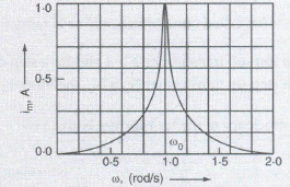
Figure shows the variation of Im with \(\omega \) in a L-C-R series circuit for two values of resistance R1 and R2(R1>R2).
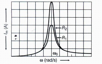
The condition for resources in the L-C-R circuit is,
XL = XC
\({ \omega }_{ 0 }L\ =\ \frac { 1 }{ { \omega }_{ 0 }C } \Rightarrow { \omega }_{ 0 }^{ 2 }=\frac { I }{ LC } \Rightarrow { \omega }_{ 0 }=\frac { 1 }{ \sqrt { LC } } \)
We see that, the current amplitude is maximum at the resonance frequency \({ \omega }_{ 0 }\) .
Since, \({ I }_{ m }=\frac { { V }_{ m } }{ R } \) ar resonance, the current amplitude for case R2
is sharper to that for case R1.
Quality factor or simply the Q-factor of a resonant L-C-R circuit is defined as the ratio of voltage drop across the capacitor (or inductor) to that of applied voltage.
It is given by \(Q=\frac { 1 }{ R } \sqrt { \frac { L }{ C } } \)
The Q-factor determines the sharpness of the resonance curve and if the resonance is less sharp, not only the maximum current becomes less, but also the circuit will be closed to the resonance for a larger range \(\triangle \omega \) frequencies and the tuning of the circuit will not be good. So, less sharp the resonance, less in the selectivity of the circuit while higher is the Q, sharper is the resonance curve and lesser will be loss in energy of the circuit.
5.
Here, \(N=100,\ A=3{ m }^{ 2 },\ \omega =60/sec.\)
\(B=0.04T,\ R=500\Omega ,\ { I }_{ 0 }=?,\ { P }_{ 0 }=?\)
\({ I }_{ 0 }=\frac { { E }_{ 0 } }{ R } =\frac { NAB\omega }{ R } =\frac { 100\times 3\times 0.04\times 60 }{ 500 } \)
\(=1.44A\)
Max. power dissipation \(={ E }_{ \upsilon }{ I }_{ \upsilon }\)
\(=\frac { { E }_{ 0 } }{ \sqrt { 2 } } \frac { { I }_{ 0 } }{ \sqrt { 2 } } =\frac { { I }_{ 0 }^{ 2 }R }{ 2 } =\frac { { \left( 1.44 \right) }^{ 2 }\times 500 }{ 2 } \)
\(=518.4 \ W\)
6.
Charge on \(\alpha \) -particle, q=+2e, where e is the charge of an electron. Thus
q = 2 x 1.6 x 10-19 C.
r = 2 x 1.6 x 10-19 C.
r = 2 x 10⁻¹⁰ m; v = 2 x 10⁶ ms-1
Current \(I=\frac { q }{ T } =\frac { q }{ 2\pi r/v } =\frac { qv }{ 2\pi r } \)
Magnetic field at the centre of circular path
\(B=\frac { { \mu }_{ o } }{ 4\pi } \frac { 2\pi I }{ 2r } =\frac { { \mu }_{ o }I }{ 2r } =\frac { { \mu }_{ o } }{ 2r } \left( \frac { qv }{ 2\pi r } \right) =\frac { { \mu }_{ o } }{ 4\pi } \frac { qv }{ { r }^{ 2 } }\)
\(=\frac { { 10 }^{ -7 }\times \left( 2\times 1.6\times { 10 }^{ -19 } \right) \times \left( 2\times { 10 }^{ 6 } \right) }{ { \left( 2\times { 10 }^{ -10 } \right) }^{ 2 } } =1.6T\)
7.
(i) 36 x 10-2 Am2
(ii) 18 x 10-2Nm
8.
Using Eq. we find
r = m v / (qB) = 9 x 10–31 kg x 3 x 107 m s–1 / ( 1.6 x 10–19 C x 6 x 10–4 T )
= 28 x 10–2 m = 28 cm
ν = v / (2 \(\pi\)r) = 17 x 106 s–1 = 17 x 106 Hz = 17 MHz.
E = (½ ) mv2 = (½ ) 9 x 10–31 kg x 9 x 1014 m2/s2 = 40.5 x 10⁻¹⁷ J
\(\approx \) 4 x 10–16 J = 2.5 keV.
9.
(i) Decreases From X to Z
(ii) Decreases From X to Z
In case of X Quality factor Is More , Impedance, Decreases From X to Z.
10.
\(|\mathrm{dB}|=\frac{\mu_{0}}{4 \pi} \frac{I \mathrm{~d} l \sin \theta}{r^{2}}\)
dl = Δx = 10−2m , I = 10 A, r = 0.5 m = y, \(\mu_{0} / 4 \pi=10^{-7} \frac{\mathrm{T} \mathrm{m}}{\mathrm{A}}\) θ = 90° ; sin θ = 1
\(|\mathrm{dB}|=\frac{10^{-7} \times 10 \times 10^{-2}}{25 \times 10^{-2}}=4 \times 10^{-8} \mathrm{~T}\)
The direction of the field is in the +z-direction. This is so since
\(\mathrm{d} \mathbf{l} \times \mathbf{r}=\Delta x \hat{\mathbf{i}} \times y \hat{\mathbf{j}}=y \Delta x(\hat{\mathbf{i}} \times \hat{\mathbf{j}})=y \Delta x \hat{\mathbf{k}}\)
We remind you of the following cyclic property of cross-products
\(\hat{\mathbf{i}} \times \hat{\mathbf{j}}=\hat{\mathbf{k}} ; \hat{\mathbf{j}} \times \hat{\mathbf{k}}=\hat{\mathbf{i}} ; \hat{\mathbf{k}} \times \hat{\mathbf{i}}=\hat{\mathbf{j}}\)
Note that the field is small in magnitude.
11.
Dia: copper, water, mercury, hydrogen. para: aluminum, oxygen.
12.
\(t=\pi / \omega=\frac{1}{2}\left(\frac{2 \pi}{\omega}\right)=\frac{T}{2} \text { and } t=\frac{2 \pi}{\omega}=T\)
\(I_{a v}=-\frac{2 I_0}{\pi}\)
13.
When an electron is moving along the direction of the magnetic field, then angle θ between velocity vector \(\vec v\) and magnetic field \(\vec B\) is zero degree, i.e.,θ=0o
Lorentz magnetic force
F=−evBsin0o=0.
14.
Gauss's law correlates surface integral of electric field \(\overset { \rightarrow }{ E } \) with charge q over a surface [i.e. \(\oint _{ s }^{ }{ \overset { \rightarrow }{ E } .\overset { \rightarrow }{ ds } } =\frac { q }{ { \in }_{ o } } \) ], whereas Ampere's law correlates the line integral of magnetic field \(\overset { \rightarrow }{ B } \) with current over a closed path [i.e. \(\oint { \overset { \rightarrow }{ B } } .\overset { \rightarrow }{ dl } ={ \mu }_{ o }I\) ].
15.
Resistance of the galvanometer coil, G = 12 Ω
Current for which there is full scale deflection, Ig = 3 mA = 3 x 10⁻³ A
Range of the voltmeter is 0, which needs to be converted to 18 V.
therefore, V = 18 V
Let a resistor of resistance R be connected in series with the galvanometer to convert it into a voltmeter. This resistance is given as:
\(R=\frac{V}{I_{\mathrm{g}}}-\mathrm{G}\)
\(=\frac{18}{3 \times 10^{-3}}-12=6000-12=5988 \Omega\)
Hence, a resistor of resistance 5998 Ω is to be connected in series with the galvanometer.
16.
Given, R1 = 10 \(\Omega\), N1 = 30, A1 = 3.6 \(\times\)10-3m2,
B1 = 0.25 T, R2 = 14 \(\Omega\), N2 = 42.
A2 = 1.8 \(\times\)10-3 m2, B2 = 0.50 T
k1 = k2 (spring constants are smae) ...(i)
(i) Using the formula of current sensitivity, \(I=\frac{N A B}{k}\)
\(\therefore \quad \frac{I_{S_2}}{I_{S_1}}=\frac{N_2 B_2 A_2 k_1}{N_1 B_1 A_1 k_2}=\frac{42 \times 0.50 \times 1.8 \times 10^{-3}}{30 \times 0.25 \times 3.6 \times 10^{-3}}\)
= 1.4 [from Eq. (i)]
(ii) Using the formula of voltage sensitivity,
\(\begin{aligned} V & =\frac{N A B}{k R} \end{aligned}\)
\(\begin{aligned} \therefore \quad \frac{V_{S_2}}{V_{S_1}} & =\frac{N_2 B_2 A_2 k_1 R_1}{k_2 R_2 N_1 B_1 A_1} \\ \end{aligned}\)
\(\begin{aligned} =\frac{42 \times 0.50 \times 1.8 \times 10^{-3} \times 10}{14 \times 30 \times 0.25 \times 3.6 \times 10^{-3}} \end{aligned}\)
= 1 [from Eq. (i)]
17.
Given, current, I = 4A
Number of turns per unit length, n = 600
Relative permeability, \(\mu \)r = 5000
Since, magnetic intensity, H = nI = 600 x 4 = 2400Am-1
Since, \(\mu\)r = 1 + Xm
\(\Rightarrow\) Xm = \(\mu\)r - 1
= 5000 -1 = 4999 \(\approx \) 5000
Here, Xm = magnetic susceptibility.
Intensity of magnetisation can be given as
I = XmH = 5000 x 2400
= 1.2 x 10⁷ Am-1
Therefore, magnetic field, B = \(\mu\)r \(\mu\)0 H
= 5000 x (4\(\pi\) x 10-7) x 2400
= 15 T
18.
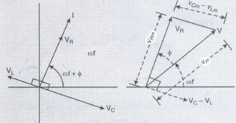
Let VL, VR, Vc and V represent the voltage across the inductor, resistor, capacitor and the source respectively. VR is parallel to I. Vc is pi/2 behind I and VL is pi/2 ahead of I.
Clearly,
\(={ i }_{ 0 }^{ 2 }[{ R }^{ 2 }+({ X }_{ L }-{ X }_{ C })^{ 2 }]\)
\({ i }_{ o }=\frac { { V }_{ 0 } }{ \sqrt { { R }^{ 2 }+({ X }_{ L }-{ X }_{ C })^{ 2 } } } \)
\(Impedence=\frac { { V }_{ 0 } }{ { i }_{ 0 } } =\sqrt { { R }^{ 2 }+({ X }_{ L }-{ X }_{ C })^{ 2 } } \)
\(\\ =\sqrt { { R }^{ 2 }+\left( \omega L-\frac { 1 }{ \omega C } \right) ^{ 2 } } \)
The capacitance of a capacitor in the tuning circuit is varied such that the resonant frequency of the circuit becomes nearly equal to the frequency of the radio signal to be received. When this happens, the amplitude of the current becomes maximum in the receiving circuit.
19.
Power is the rate of doing work. In A.C current and voltage change at every moment. Since power is the product of instantaneous voltage and current, therefore it changes at every moment.
To determine average power in a circuit containing pure resistor, determine total energy spent in one cycle and divide it by the period.
Instantaneous power \(=EI=\left[ { E }_{ 0 }sin\omega t \right] \left[ { I }_{ 0 }sin\omega t \right] \)
Instantaneous work done in small interval dt is
\( \ dW=EI \ dt={ E }_{ 0 }{ I }_{ 0 }{ sin }^{ 2 }\omega t \ dt\)
\(W=\int _{ 0 }^{ T }{ { E }_{ 0 }{ I }_{ 0 }{ sin }^{ 2 }\omega t \ dt }\)
\(W={ E }_{ 0 }{ I }_{ 0 }\int _{ 0 }^{ T }{ { \left( \frac { 1-cos2\omega t }{ 2 } \right) }dt } \)
\(=\left[ \because \int _{ 0 }^{ T }{ dt } -\int _{ 0 }^{ T }{ cos2\omega t } \right]\)
\(or \ \ W=\frac { { E }_{ 0 }{ I }_{ 0 } }{ 2 } \left[ T-0 \right] =\frac { { E }_{ 0 }{ I }_{ 0 } }{ 2 } T\)
\( \left[ \because \int _{ 0 }^{ T }{ dt } -\int _{ 0 }^{ T }{ cos2\omega t } \right] =0\)
\(or \ \ { P }_{ av }=\frac { W }{ T } =\frac { { E }_{ 0 }{ I }_{ 0 } }{ 2 } =\frac { { E }_{ 0 } }{ \sqrt { 2 } } .\frac { { I }_{ 0 } }{ \sqrt { 2 } } \)
\(\ {P }_{ av }={ E }_{ v }{ I }_{ v }\)
\(\therefore\) Average power over a complete cycle of a.c through a resistor is the product of virtual voltage and virtual current.
20.
(d)
X is diamagnetic and Y is paramagnetic
21.
(a)
G/200
22.
(c)
\(\vec { E } \parallel \vec { B } \), \(\vec { \upsilon } \parallel \vec { E } \)
23.
(d)
voltage and current possibly differing in phase \(\phi \) such that \(\left| \phi \right| <\frac { \pi }{ 2 } \)
24.
(d)
Zero
25.
(b)
\(\frac { { \mu }_{ o }nI }{ 2r } \)
26.
(b)
anticlockwise
27.
(a)
\(\frac { 1 }{ R } \sqrt { \frac { L }{ C } } \)
28.
(I) (b): Inductance, L = 80 mH = 80 x 10-3 H
Capacitance, C = \(60 \mu \mathrm{F}=60 \times 10^{-6} \mathrm{~F}, V=230 \mathrm{~V}\)
Frequency, u = 50 Hz
\(\omega=2 \pi v=100 \pi \mathrm{rad} \mathrm{s}^{-1}\)
Peak voltage \(V_{0}=V \sqrt{2}=230 \sqrt{2} \mathrm{~V}\)
Maximum current is given by, \(I_{0}=\frac{V_{0}}{\left(\omega L-\frac{1}{\omega C}\right)}\)
\(I_{0}=\frac{230 \sqrt{2}}{\left(100 \pi \times 80 \times 10^{-3}-\frac{1}{100 \pi \times 60 \times 10^{-6}}\right)}\)
Amplitude of maximum current, Io = 11.63 A
(ii) (c): rms value of current,
\(I=\frac{I_{0}}{\sqrt{2}}=\frac{-11.63}{\sqrt{2}}=-8.23 \mathrm{~A}\)
Negative sign appears as \(\omega L<\frac{1}{\omega C}\)
(iii) (a): Average power consumed by the inductor is zero because of phase difference of \(\frac{\pi}{2}\) between voltage and current through inductor.
(iv) (b): Average power consumed by the capacitor is zero because of phase difference of \(\frac{\pi}{2}\) between voltage and current through capacitor
(v) (a)
29.
(i) (d): A galvanometer can be converted into a voltmeter of given range by connecting a suitable high resistance R in series of galvanometer, which is given by
\(R=\frac{V}{I_{g}}-G=\frac{100}{10 \times 10^{-3}}-25=10000-25=9975 \Omega\)
(ii) (c): An ideal voltmeter should have a very high resistance.
(iii) (c): Resistance of voltmeter \(=\frac{25}{25 \times 10^{-3}}=1000 \Omega\)
\(\therefore \quad X=1000-10=990 \Omega\)
(iv) (d): To convert a moving coil galvanometer into a voltmeter, it is connected with a high resistance in series. The voltmeter is connected in parallel to measure the potential difference. As the resistance is high, the voltmeter itself does not consume current.
(v) (d): The resistance of an ideal voltmeter is infinity.
30.
31.
A) Both A and R are true and R is the correct explanation of A
32.
(c): The transmission is done at high voltage due to which current through the wire is reduced By reduction in current corresponding dissipation of energy is also reduced \(\left(\text { as } H \propto I^{2} R\right)\) If transmissioh is done at low voltage then we have to use thick wire-in order to reduce the dissipation of energy. This increase the cost of transmission lines wires. In order to reduce both energy dissipation and cost of transmission wire, transmission is done at high voltage by using step-up transformers.
33.
(a): The magnetic field at the centre of circular coil is given by
\(B=\frac{\mu_{0}}{4 \pi} \frac{2 \pi n I}{a}\)
So if current through coil is doubled then magnetic field is \(B^{\prime}=2 B\)
The magnetic field also get doubled. The magnetic field is directly proportional to the current in conductor

12th Standard CBSE Syllabus & Materials
12th Standard CBSE
CBSE 12th Computer Science Python Revision Tour I - New Previous year Question Papers Study Material - QB365 Set A
NEW12th Standard CBSE
CBSE 12th Business Studies Planning Important Questions And Answers Study Material - QB365 Set A
NEW12th Standard CBSE
CBSE 12th Business Studies Business Environment Important Questions And Answers Study Material - QB365 Set A
NEW12th Standard CBSE
CBSE 12th Business Studies Principles of Management Important Questions And Answers Study Material - QB365 Set A



NCERT Books

Syllabus

Exam Pattern

Sample Question Papers

Previous year Question Papers

Important Notes

MCQ Practice test

NCERT Exemplers

Case study Questions

Image Based Questions

Passage based Questions

HOT Questions

Value Based Questions

Model Questions Papers
NCERT ( Book Back ) Questions

Assertion and Reason
Important Questions And Answers

CBSE 12th Standard CBSE Subjects
CBSE Standards