


CBSE 12th Standard Physics Subject Alternating Current Chapter Case Study Questions With Solution 2021
QB365 Provides the updated CASE Study Questions for Class 12 , and also provide the detail solution for each and every case study questions . Case study questions are latest updated question pattern from NCERT, QB365 will helps to get more marks in Exams
QB365 - Question Bank Software
CBSE 12th Standard Physics Subject Alternating Current Case Study Questions With Solution 2021
12th Standard CBSE
-
Reg.No. :
Physics
-
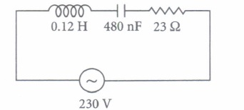
When the frequency of ac supply is such that the inductive reactance and capacitive reactance become equal, the impedance of the series LCR circuit i equal to the ohmic resistance in the circuit. Such a series LCR circuit is known as resonant series LCR circuit and the frequency of the ac supply is known as resonant frequency
Resonance phenomenon is exhibited by a circuit only ifboth Land C are present in the circuit. We cannot have resonance in a RL or RC circuit
A series LCR circuit with \(L=0.12 \mathrm{H}, C=480 \mathrm{nF}, R=23 \Omega\) is connected to a 230 V variable frequency supply
(i) Find the value of source frequency for which current amplitude is maximum(a) 222.32 Hz (b) 550.52 Hz (c) 663.48 Hz (d) 770 Hz (ii) The value of maximum current is
(a) 14.14 A (b) 22.52 A (c) 50.25 A (d) 47.41 A (iii) The value of maximum power is
(a) 2200 W (b) 2299.3 W (c) 5500 W (d) 4700 W (iv) What is the Q-factor of the given circuit?
(a) 25 (b) 42.21 (c) 35.42 (d) 21.74 (v) At resonance which of the following physical quantity is maximum?
(a) Impedance (b) Current (c) Both (a) and (b) (d) Neither (a) nor (b) -
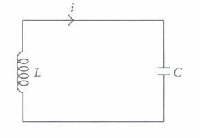
An LC circuit also called a resonant circuit, tank circuit or tuned circuit is an electric circuit consisting of an inductor represented by the letter L and a capacitor, represented by the letter C connected together. An LC circuit is an idealized model since it assumes there is no dissipation of energy due to resistance.
An LC circuit contains a 20 mH inductor and a \(50 \mu \mathrm{F}\) capacitor with an initial charge of 10 mC The resistance of the circuit is negligible. Let the instant the circuit is closed be t = 0.
(i) The total energy stored initially is(a) 5 J (b) 3 J (c) 10 J (d) 1 J (ii) The natural frequency of the circuit is
(a) 159.24 Hz (b) 200.12 Hz (c) 110.25 Hz (d) 95 Hz (iii) At what time is the energy stored completely electrical?
\(\text { (a) } T, 5 T, 9 T\) \(\text { (b) } \frac{T}{2}, \frac{5 T}{2}, \frac{9 T}{2}\) (c) 0, T, 2T, 3T \(\text { (d) } 0, \frac{T}{2}, T, \frac{3 T}{2}\) (iv) At what time is the energy stored completely magnetic?
\(\text { (a) } \frac{T}{2}, \frac{3 T}{2}, \frac{T}{4}\) \(\text { (b) } \frac{T}{3}, \frac{T}{9}, \frac{T}{12}\) (c) 0, 2T, 3T \(\text { (d) } \frac{T}{4}, \frac{3 T}{4}, \frac{5 T}{4}\) (v) The value of XL is
\(\text { (a) } 20 \Omega\) \(\text { (b) } 40 \Omega\) \(\text { (c) } 60 \Omega\) \(\text { (d) } 50 \Omega\) -
Step-down transformers are used to decrease or step-down voltages. These are used when voltages need to be lowered for use in homes and factories.
A small town with a demand of 800 kW of electric power at 220 V is situated 15 km away from an electric plant generating power at 440 V. The resistance of the two wire line carrying power is \(0.5 \Omega\) per km. The town gets power from the line through a 4000 - 220 V step-down transformer at a sub-station in the town.
(i) The value of total resistance of the wires is\(\text { (a) } 25 \Omega\) \(\text { (b) } 30 \Omega\) \(\text { (c) } 35 \Omega\) \(\text { (d) } 15 \Omega\) (ii) The line power loss in the form of heat is
(a) 550 kW (b) 650 kW (c) 600 kW (d) 700 kW (iii) How much power must the plant supply, assuming there is negligible power loss due to leakage?
(a) 600 kW (b) 1600 kW (c) 500 W (d) 1400 kW (iv) The voltage drop in the power line is
(a) 1700V (b) 3000V (c) 2000V (d) 2800 V (v) The total value of voltage transmitted from the plant is
(a) 500 V (b) 4000 V (c) 3000 V (d) 7000 V -
In an a.c. circuit, values of voltage and current change every instant. Therefore, power of an a.c. circuit at any instant is the product of instantaneous voltage (E) and instantaneous current (I). The average power supplied to a pure resistance R over a complete cycle of a.c. is \(P=E_{v} I_{v}\) When circuit is inductive, average power per cycle is \(E_{v} I_{v} \cos \phi\)
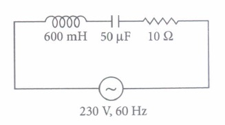
In an a.c. circuit, 600 mH inductor and a \(50 \mu \mathrm{F}\) capacitor are connected in series with \(10 \Omega\) nresistance. The a.c. supply to the circuit is 230 V, 60 Hz.
(i) The average power transferred per cycle to resistance is(a) 10.42 W (b) 15.25 W (c) 17.42 W (d) 13.45 W (ii) The average power transferred per cycle to capacitor is
(a) zero (b) 10.42 W (c) 17.42 W (d) 15W (iii) The average power transferred per cycle to inductor is
(a) 25W (b) 17.42 W (c) 16.52 W (d) zero (iv) The total power transferred per cycle by all the three circuit elements is
(a) 17.42 W (b) 10.45W (c) 12.45 W (d) zero (v) The electrical energy spend in running, the circuit for one hour is
(a) 7.5 x 10⁵ Joule (b) 10 x 103 Joule (c) 9.4 x 10³ Joule (d) 6.2 x 10⁴ Joule -
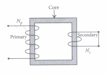
A transformer is an electrical device which is used for changing the a.c. voltages. It is based on the phenomenon of mutual induction i.e. whenever the amount of magnetic flux linked with a coil changes, an e.m.f is induced in the neighbouring coil. For. an ideal transformer, the resistances of the primary and secondary windings are negligible.
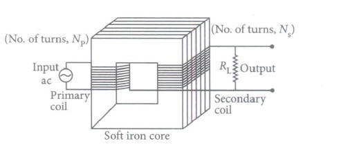
It can be shown that \(\frac{E_{s}}{E_{p}}=\frac{I_{p}}{I_{s}}=\frac{n_{s}}{n_{p}}=k\)
where the symbols have their standard meanings.
For a step up transformer \(n_{s}>n_{p} ; E_{s}>E_{p} ; k>1 ; \quad \therefore I_{s}
For a step down transformer \(n_{s}
The above relations are on the assumptions that efficiency of transformer is 100%.
lentlac ,effciency \(\eta=\frac{\text { output power }}{\text { intput power }}=\frac{E_{s} I_{s}}{E_{p} I_{p}}\)
(i) Which of the following quantity remains constant in an ideal transformer?(a) Current (b) Voltage (c) Power (d) All of these (ii) Transformer is used to
(a) convert ac to dc voltage (b) convert de to ac voltage (c) obtain desired dc power (d) obtain desired ac voltage and current (iii) The number of turns in primary coil of a transformer is 20 and the number of turns in a secondary is 10. If the voltage across the primary is 220 ac V, what is the voltage across the secondary?
(a) 100 ac V (b) 120 ac V (c) 110 ac V (d) 220 ac V (iv) In a transformer the number of primary turns is four times that of the secondary turns. Its primary is connected to an a.c. source of voltage V. Then
(a) current through its secondary is about four times that of the current through its primary (b) voltage across its secondary is about four times that of the voltage across its primary. (c) voltage across its secondary is about two times that of the voltage across its primary (d) voltage across its secondary is about \(\frac{1}{2 \sqrt{2}}\) times that of the voltage across its primary (v) A transformer is used to light 100 W-110 V lamp from 220 V mains. If the main current is 0.5 A, the efficiency of the transformer is
(a) 95% (b) 99% (c) 90% (d) 96%
Part A
*****************************************
CBSE 12th Standard Physics Subject Alternating Current Case Study Questions With Solution 2021 Answer Keys
-
(i) (c) : Here \(L=0.12 \mathrm{H}, C=480 \mathrm{nF}^{\prime}=480 \times 10^{-9} \mathrm{~F}\)
\(R=23 \Omega, V=230 \mathrm{~V}\)
\(V_{0}=\sqrt{2} \times 230=325.22 \mathrm{~V}\)
\(I_{0}=\frac{V_{0}}{\sqrt{R^{2}+\left(\omega L-\frac{1}{\omega C}\right)^{2}}}\)
At resonance, \(\omega L-\frac{1}{\omega C}=0\)
\(\omega=\frac{1}{\sqrt{L C}}=\frac{1}{\sqrt{0.12 \times 480 \times 10^{9}}}=4166.67 \mathrm{rad} \mathrm{s}^{-1}\)
\(v_{R}=\frac{4166.67}{2 \times 3.14}=663.48 \mathrm{~Hz}\)
(ii) (a) : Current \(I_{0}=\frac{V_{0}}{R}=\frac{325.22}{23}=14.14 \mathrm{~A}\)
(iii) (b) : Maximum power \(P_{\max }=\frac{1}{2}\left(I_{0}\right)^{2} R\)
\(=\frac{1}{2} \times(14.14)^{2} \times 23=2299.3 \mathrm{~W}\)
(iv) (d) : Quality factor \(Q=\frac{X_{L}}{R}=\frac{\omega_{r} L}{R}\)
\(=\frac{4166.67 \times 0.12}{23}=21.74\)
(v) (b) -
(i) (d):Energy, \(E=\frac{1}{2} \frac{Q^{2}}{C}=\frac{\left(10 \times 10^{-3}\right)^{2}}{2 \times 50 \times 10^{-6}}=1 \mathrm{~J}\)
(ii) (a): Frequency \(v=\frac{1}{2 \pi \sqrt{L C}}\)
\(=\frac{1}{2 \pi \sqrt{20 \times 10^{-3} \times 50 \times 10^{-6}}}=\frac{10^{3}}{2 \pi}=159.24 \mathrm{~Hz}\)
(iii) (d): Total time period \(T=\frac{1}{v}=\frac{1}{159.24}=6.28 \mathrm{~ms}\)
Total charge on capacitor at time t \(Q^{\prime}=Q \cos \frac{2 \pi}{T} t\)
For energy stored is electrical, we can write \(Q^{\prime}=\pm Q\)
Hence, energy stored in the capacitor is completely electrical at \(t=0, \frac{T}{2}, T, \frac{3 T}{2}, \ldots .\)
(iv) (d): Magnetic energy is maximum when electrical energy is equal to zero
Hence \(t=\frac{T}{4}, \frac{3 T}{4}, \frac{5 T}{4}\)
(v) (a): \(X_{L}=\omega L=2 \pi \cup L=2 \times 3.14 \times 159.24 \times 20\) x 10-3
\(\Rightarrow \quad X_{L}=20 \Omega\) -
(i) (d): Resistance of the two wire lines carrying power \(=0.5 \Omega / \mathrm{km}\)
Total resistance \(=(15+15) 0.5=15 \Omega\)
(ii) (c): Line power loss = I2R
RMS current in the coil,
\(I=\frac{P}{V_{1}}=\frac{800 \times 10^{3}}{4000}=200 \mathrm{~A}\)
\(\therefore\) Power loss \(=(200)^{2} \times 15=600 \mathrm{~kW}\)
(iii) (d): Assuming that the power loss is negligible due to the leakage of the current.
The total power supplied by the plant
= 800 kW + 600 kW = 1400 kW
(iv) (b): Voltage drop in the power line = IR
= 200 x 15 = 3000 V
(v) (d): Total voltage transmitted from the plant = 3000 V + 4000 V = 7000 V -
(i) (c): Average power transferred per cycle to resistance is \(P_{v}=I_{v}^{2} R\)
As \(X_{L}=\omega L=2 \pi \cup L=2 \times \frac{22}{7} \times 60 \times 0.6=226.28 \Omega\)
\(X_{C}=\frac{1}{\omega C}=\frac{1}{2 \pi v C}=\frac{1}{2 \times 22 / 7 \times 60 \times 50 \times 10^{-6}}\)
\(=53.03 \Omega\)
\(Z=\sqrt{R^{2}+\left(X_{L}-X_{C}\right)^{2}}\)
\(=\sqrt{(10)^{2}+(226.28-53.03)^{2}}=173.53 \Omega\)
\(I_{v}=\frac{E_{v}}{Z}=\frac{230}{173.53}=1.32 \mathrm{~A}\)
\(P_{v}=I_{v}^{2} R=(1.32)^{2} \times 10=17.42 \mathrm{~W}\)
(ii) (a) : \(P_{C}=E_{v} I_{v} \cos \phi\)
In a capacitor, phase difference \(\phi=90^{\circ}\)
\(\therefore \quad P_{L}=E_{v} I_{v} \cos 90^{\circ}=\text { zero }\)
(iii) (d): \(P_{L}=E_{\gamma} I_{v} \cos \phi\)
In an inductor, phase difference \(\phi=90^{\circ}\)
\(P_{L}=E_{\nu} I_{v} \cos 90^{\circ}=\text { zero }\)
(iv) (a): Total power absorbed per cycle
\(P=P_{R}+P_{C}+P_{L}=17.42+0+0=17.42 \mathrm{~W}\)
(v) (d): Energy spent = power x time
\(=17.42 \times 60 \times 60=6.2 \times 1,0^{4} \text { Joule }\) -
(i) (c) :In an ideal transformer, there is no power loss. The efficiency of an ideal transformer is \(\eta=1(i . e\) 100%) i.e. input power = output power.
(ii) (d): Transformer is used to obtain desired ac voltage and current.
(iii) (c): For a transformer \(\frac{V_{s}}{V_{p}}=\frac{N_{s}}{N_{p}}\)
where Ndenotes number of turns and V = voltage
\(\therefore \frac{V_{s}}{220}=\frac{10}{20} \quad \therefore V_{s}=110 \mathrm{ac} \mathrm{V}\)
(iv) (a): In a transformer the primary and secondary currents are related by
\(I_{s}=\left(\frac{N_{p}}{N_{s}}\right) I_{p}\)
and the voltages are related by
\(V_{s}=\left(\frac{N_{s}}{N_{p}}\right) V_{p}\)
where subscripts p and s refer to the primary and secondary of the transformer
Here, \(V_{p}=V, \frac{N_{p}}{N_{s}}=4 \quad \therefore \quad I_{s}=4 I_{p}\)
and \(V_{s}=\left(\frac{1}{4}\right) V=\frac{V}{4}\)
(v) (c): The efficiency of the transformer is \(\eta=\frac{\text { Output power }\left(P_{\text {out }}\right)}{\text { Input power }\left(P_{\text {in }}\right)} \times 100\)
Here, \(P_{\text {out }}=100 \mathrm{~W}, P_{\text {in }}=(220 \mathrm{~V})(0.5 \mathrm{~A})=110 \mathrm{~W}\)
\(\therefore \quad \eta=\frac{100 \mathrm{~W}}{110 \mathrm{~W}} \times 100 \approx 90 \%\)
Part A