CBSE 12th Standard Physics Subject Alternating Current HOT Questions 3 Mark Questions 2021
By QB365 on 27 May, 2021
QB365 Provides the HOT Question Papers for Class 12 Physics, and also provide the detail solution for each and every HOT Questions. HOT Questions will help to get more idea about question pattern in every exams and also will help to get more marks in Exams
QB365 - Question Bank Software
CBSE 12th Standard Physics Subject Alternating Current HOT Questions 3 Mark Questions 2021
12th Standard CBSE
-
Reg.No. :
Physics
-
A 12 V resistance and an inductance of \(\frac { 0.05 }{ \pi } H\) are connected in series.Across the end of this ciuit an alternating voltage of 130 V and frequency 50 Hz is connected. Calculate the current in the circuit and the potential difference across the inductance.
(a) -
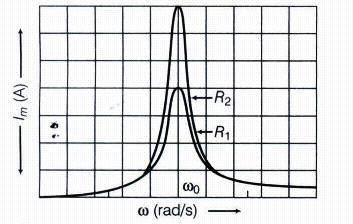
In a series L-C-R circuit connected to an AC source of variable frequency and voltage \(V\ =\ { V }_{ m }\ sin\ \omega t\), draw a plot showing the variation of current I with angular frequency \(\omega \), for two different values of resistance R1and R2(R1>R2). Write the condition under which the phenomenon of resistance occurs. For which value of the resistance out of the two curves, a sharper resonance is produced? Define Q-factor of the circuit and give its significance.
(a) -
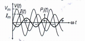
An AC voltage \(V={ V }_{ m }sin \ \omega t\) is applied across an inducer of inductance L.Find the instantaneous power Pi supplied to the inductor. Show graphically the variation of Pi with \(\omega t\) .
(a) -
(i) Determine the value of phase difference between the current and the voltage in the given series L-C-R circuit.

(ii) Calculate the Value of additional capacitor which may be joined suitably to the capacitor C that would make the power factor of the circuit unity.(a) -
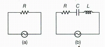
Study the circuits (a) and (b) shown in the figure answer the following question:

(i) Under which conditions would the rms currents in the two circuits be the same?
(ii) Can the rms current in circuit (b) be larger than that in (a)?(a)
*****************************************
CBSE 12th Standard Physics Subject Alternating Current HOT Questions 3 Mark Questions 2021 Answer Keys
-
\( { I }_{ v }=\frac { { E }_{ v } }{ Z } =\frac { 130 }{ 2 } \ \ ...(i)\)
\(Since \ \ Z=\sqrt { { R }^{ 2 }+{ X }_{ L }^{ 2 } } =\sqrt { { \left( 12 \right) }^{ 2 }{ +\left( 2\pi vL \right) }^{ 2 } }\)
\(=\sqrt { { \left( 12 \right) }^{ 2 }+{ \left( 2\pi \times 50\times \frac { 0.05 }{ \pi } \right) }^{ 2 } } \)
\(or \ Z=\sqrt { 144+{ \left( 5 \right) }^{ 2 } } =13\Omega \)
\(So \ \ { I }_{ v } \ =\frac { 130 }{ 13 } =10 \ A\)
\(\\ And \ \ { E }_{ L }={ X }_{ L }I=5\times 10=50 \ V\) -
Figure shows the variation of Im with \(\omega \) in a L-C-R series circuit for two values of resistance R1 and R2(R1>R2).

The condition for resources in the L-C-R circuit is,
XL = XC
\({ \omega }_{ 0 }L\ =\ \frac { 1 }{ { \omega }_{ 0 }C } \Rightarrow { \omega }_{ 0 }^{ 2 }=\frac { I }{ LC } \Rightarrow { \omega }_{ 0 }=\frac { 1 }{ \sqrt { LC } } \)
We see that, the current amplitude is maximum at the resonance frequency \({ \omega }_{ 0 }\) .
Since, \({ I }_{ m }=\frac { { V }_{ m } }{ R } \) ar resonance, the current amplitude for case R2
is sharper to that for case R1.
Quality factor or simply the Q-factor of a resonant L-C-R circuit is defined as the ratio of voltage drop across the capacitor (or inductor) to that of applied voltage.
It is given by \(Q=\frac { 1 }{ R } \sqrt { \frac { L }{ C } } \)
The Q-factor determines the sharpness of the resonance curve and if the resonance is less sharp, not only the maximum current becomes less, but also the circuit will be closed to the resonance for a larger range \(\triangle \omega \) frequencies and the tuning of the circuit will not be good. So, less sharp the resonance, less in the selectivity of the circuit while higher is the Q, sharper is the resonance curve and lesser will be loss in energy of the circuit. -
In an inductor, the current lags the voltage by 900 . If the source voltage is sinusoidal, then the current is also sinusoidal but shifted in phase. The instantaneous power defined as the product of the instantaneous voltage and current can also be seen to be sinusoidal in time. However, in contrast to the resistive load, the instantaneous power in the inductor goes negative for part of the cycle of the source driving it.
As, \(V(t)={ V }_{ m }\sin { \omega t } \)
\(I(t)=-{ I }_{ m }cos\omega t\)
instantaneous power Pi = V(t).I(t)
\(={ V }_{ m }sinn\omega t\times (-{ I }_{ m }cos\omega t)\)
\(=-\frac { { V }_{ m }{ I }_{ m } }{ 2 } \times 2sin\omega tcos\omega t\)
\(=-\frac { { V }_{ m }{ I }_{ m } }{ 2 } [sin\omega t+sin\ 0]\)
\(=-\frac { { V }_{ m }{ I }_{ m } }{ 2 } sin2\omega t\)
The variation of Pi with \(\omega t\) is as given in the figure.

The instantaneous power altertes positive and negative at twice the ferquency of source supplying it. -
(i) Consider the given figure,

Since, the alternating emf in the above L-C-R series circuit would be represented by
\(V={ V }_{ 0 }sin(1000t+\phi )\)
\(\Rightarrow \omega =1000Hz \)
Given, \(R=400\Omega ,C=2\mu F,L=100mH\)
Capacitive reactance, \({ X }_{ C }=\frac { 1 }{ \omega C } \)
\(\Rightarrow \ \ { X }_{ C }=\frac { 1 }{ 1000\times 2\times { 10 }^{ -6 } } \Rightarrow \quad { X }_{ C }=\frac { { 10 }^{ 3 } }{ 2 } \)
\(\Rightarrow \ \ { X }_{ L }=1000\times 100\times { 10 }^{ -3 }=100\Omega \)
So, we can see that \(\Rightarrow \ \ { X }_{ C }=\omega L\)
\(\Rightarrow \ tan\phi \) is negative.
Hence, the Voltage lags behind the current by a phase angle \( \phi \).The AC circuit is capacitance-dominated circuit.
Phase difference \(tan\ \phi \ =\frac { { X }_{ L }-{ X }_{ C } }{ R } \)
\(tan \ \phi \ =\frac { 100-500 }{ 400 } \Rightarrow tan \ \phi =\frac { -400 }{ 400 } \)
\(tan \ \phi \ =-1 \ \ \Rightarrow tan \ \phi =-tan\left( \frac { \pi }{ 4 } \right) \)
\(\Rightarrow \ \ \phi =-\frac { \pi }{ 4 } \)
This is the required value of the phase difference between the current and the voltage in the given series L-C-R circuit.
As, \(cos\phi <1\)
(ii) Suppose new capacitance of the circuit is C'.
\(cos\phi '=1=\frac { 1 }{ \sqrt { { R }^{ 2 }+\left( { X }_{ L }-{ X }_{ C }^{ ' } \right) ^{ 2 } } } \)
\(\Rightarrow \ { R }^{ 2 }={ R }^{ 2 }+{ R }^{ 2 }+\left( { X }_{ L }-{ X }_{ C }^{ ' } \right) ^{ 2 }\)
\(\Rightarrow \ { X }_{ L }={ X }_{ C }^{ , }=\frac { 1 }{ \omega C' } or\quad \omega L=\frac { 1 }{ \omega C' } \)
\(\Rightarrow \quad { \omega }^{ 2 }=\frac { 1 }{ LC' } \)
or \(\Rightarrow \ (1000)^{ 2 }=\frac { 1 }{ LC' } \quad [\omega =1000]\)
\(\Rightarrow \ C^{ ' }=\frac { 1 }{ L\times { 10 }^{ 6 } } =\frac { 1 }{ 100\times { 10 }^{ -3 }\times { 10 }^{ 6 } } \)
\(\Rightarrow \ \frac { 10 }{ { 10 }^{ 6 } } =\frac { 1 }{ { 10 }^{ 5 } } ={ 10 }^{ -5 }\)
\(\Rightarrow \ C'={ 10 }^{ -5 }F\ =10\times { 10 }^{ -6 }F=10\mu F\)
As, C' > C. Hence, we have to add an additional capacitor \(10\mu F(10\mu F-2\mu F)\) in parallel with previous capacitor. -
Let (Irms)a = rms current in circuit (a)
(Irms)b = rms current in circuit (b)
\({ \left( I_{ rms } \right) }_{ a }=\frac { { V }_{ rms } }{ Z } =\frac { V }{ R } \)
\({ \left( I_{ rms } \right) }_{ b }=\frac { { V }_{ rms } }{ Z } b\)
\(=\frac { V }{ \sqrt { { R }^{ 2 }+\left( { X }_{ L }-{ X }_{ C } \right) ^{ 2 } } } \)
When \(({ I }_{ rms })_{ a } =({ I }_{ rms })_{ b }\)
\(R=\sqrt { { R }^{ 2 }+\left( { X }_{ L }-{ X }_{ C } \right) ^{ 2 } } \)
\(\Rightarrow \ { X }_{ L }={ X }_{ C }\) in resonance condition
(ii) As, \( Z\ge R\)
\(\Rightarrow \frac { ({ I }_{ rms })_{ a } }{ ({ I }_{ rms })_{ a } } =\frac { \sqrt { R=\sqrt { { R }^{ 2 }+\left( { X }_{ L }-{ X }_{ C } \right) ^{ 2 } } } }{ R } \)
\(=\frac { Z }{ R } \ \ge 1\)
\(({ I }_{ rms })_{ a }\ge ({ I }_{ rms })_{ b }\)
No, the rms current in circuit (b) cannot be larger than that in (a)


