Class 10th Science - Electricity Case Study Questions and Answers 2022 - 2023
By QB365 on 09 Sep, 2022
QB365 provides a detailed and simple solution for every Possible Case Study Questions in Class 10 Science Subject - Electricity, CBSE. It will help Students to get more practice questions, Students can Practice these question papers in addition to score best marks.
QB365 - Question Bank Software
Electricity Case Study Questions With Answer Key
10th Standard CBSE
-
Reg.No. :
Science
-
The rate of flow of charge is called electric current. The SI unit of electric current is Ampere (A). The direction of flow of current is always opposite to the direction of flow of electrons in the current.
The electric potential is defined as the amount of work done in bringing a unit positive test charge from infinity to a point in the electric field. The amount of work done in bringing a unit positive test charge from one point to another point in an electric field is defined as potential difference.
\(\begin{equation} V_{A B}=V_{B}-V_{A}=\frac{W_{B A}}{q} \end{equation}\)
The SI unit of potential and potential difference is volt.
(i) The 2 C of charge is flowing through a conductor in 100 rns, the current in the circuit is(a) 20 A (b) 2 A (c) 0.2 A (d) 0.02 A (ii) Which of the following is true?
(a) Current flows from positive terminal of the cell to the negative terminal of the cell outside the cell.
(b) The negative charge moves from lower potential to higher potential.
(c) The direction of flow of current in same as the direction of flow of positive charge.
(d) All of these
(iii) The potential difference between the two terminals of a battery, if 100 joules of work is required to transfer 20 coulombs of charge from one terminal of the battery to other is(a) 50 V (b) -5 V (c) 0.5 V (d) 500 V (iv) The number of electrons flowing per second in a conductor if 1A current is passing through it
(a) 6.25 x 10²⁰ (b) 6.25 x 10¹⁹ (c) 6.25 X 10¹⁸ (d) 6.25 x 10⁻¹⁹ (v) The voltage can be written as
(a) Work done x charge x time (b) \(\begin{equation} \frac{\text { Work done }}{\text { Current } \times \text { time }} \end{equation}\) (c) \(\begin{equation} \frac{\text { Work done } \times \text { time }}{\text { Current }} \end{equation}\) (d) Work done x charge (a) -
The relationship between potential difference and current was first established by George Simon Ohm called Ohm's law. According to this law, the current through a metallic conductor is proportional to the potential difference applied between its ends, provided the temperature remain constant i.e. I \(\begin{equation} \propto \end{equation}\) V or V = IR; where R is constant for the conductor and it is called resistance of the conductor. Although Ohm's law has been found valid over a large class of materials, there do exist materials and devices used in electric circuits where the proportionality of V and I does not hold.
(i) If both the potential difference and the resistance in a circuit are doubled, then(a) current remains same (b) current is doubled (c) current is halved (d) current is quadrupled (ii) For a conductor, the graph between V and I is there. Which one is the correct?
(a) 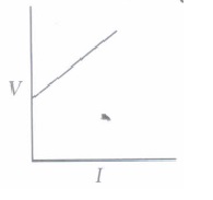
(b) 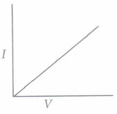
(c) 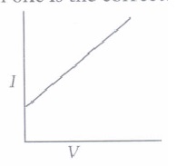
(d) 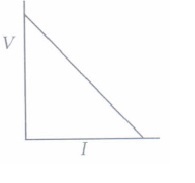
(iii) The slope of V - I graph (V on x-axis and I on y-axis) gives
(a) resistance (b) reciprocal of resistance (c) charge (d) reciprocal of charge. (iv) When battery of 9 V is connected across a conductor and the current flows is 0.1 A, the resistance is
(a) 9 \(\begin{equation} \Omega \end{equation}\) (b) 0.9 \(\begin{equation} \Omega \end{equation}\) (c) 90 \(\begin{equation} \Omega \end{equation}\) (d) 900 \(\begin{equation} \Omega \end{equation}\) (v) By increasing the voltage across a conductor, the
(a) current will decrease (b) resistance will increase (c) current will increase (d) resistance will decrease. (a) -
The obstruction offered by a conductor in the path of flow of current is called resistance. The SI unit of resistance is ohm (\(\begin{equation} \Omega \end{equation}\)). It has been found that the resistance of a conductor depends on the temperature of the conductor. As the temperature increases the resistance also increases. But the resistance of alloys like mangnin, constantan and nichrome is almost unaffected by temperature. The resistance of a conductor also depends on the length of conductor and the area of cross-section of the conductor. More be the length, more will be the resistance, more be the area of cross-section, lesser will be the resistance.
(i) Which of the following is not will desired in material being used for making electrical wires?(a) High melting point (b) High resistance (c) High conductivity (d) None of these (ii) The V - I graph for two metallic wires A and B is given. What is the correct relationship between their temperatures?
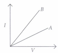
(a) TA < TB (b) TA > TB (c) TA = TB (d) none of these (iii) Two wires of same material one of length L and area of cross-section A, other is of length 2L and area A/2 . Which of the following is correct?
(a) R1 = R2 (b) R1 = 4R2 (c) R2 = 4R1 (d) R1 = 2R2 (iv) For the same conducting wire
(a) resistance is higher in summer
(b) resistance is higher in winter
(c) resistance is same is summer or in winter
(d) none of these
(v) A wire of resistance 20 \(\begin{equation} \Omega \end{equation}\) is cut into 5 equal pieces. The resistance of each part is(a) 4 \(\begin{equation} \Omega \end{equation}\) (b) 10 \(\begin{equation} \Omega \end{equation}\) (c) 100 \(\begin{equation} \Omega \end{equation}\) (d) 80 \(\begin{equation} \Omega \end{equation}\) (a) -
Two or more resistances are connected in series or in parallel or both, depending upon whether we want to increase or decrease the circuit resistance.
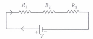
The two or more resistances are said to be connected in series if the current flowing through each resistor is same. The equivalent resistance in the series combination is given by
Rs = R1 + R2 + R3
(i) When three resistors are connected in series with a battery of voltage V and voltage drop across resistors is V1, V2 and V3, which of the relation is correct?(a) V = V1= V2 = V3 (b) V = V1 + V2 + V3 (c) V1 + V2 + V3 = 3V (d) V > V1 + V2 + V3 (ii) When the three resistors each of resistance R ohm, connected in series, the equivalent resistance is
(a) R/2 (b) > R (c) < R/2 (d) < R (iii) There is a wire oflength 20 cm and having resistance 20 \(\begin{equation} \Omega \end{equation}\) cut into 4 equal pieces and then joined in series.
The equivalent resistance is(a) 20 \(\begin{equation} \Omega \end{equation}\) (b) 4 \(\begin{equation} \Omega \end{equation}\) (c) 5 \(\begin{equation} \Omega \end{equation}\) (d) 10 \(\begin{equation} \Omega \end{equation}\) (iv) In the following circuit, find the equivalent resistance between A and B is (R = 2 \(\begin{equation} \Omega \end{equation}\))
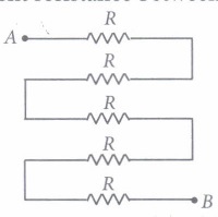
(a) 10 \(\begin{equation} \Omega \end{equation}\) (b) 5 \(\begin{equation} \Omega \end{equation}\) (c) 2 \(\begin{equation} \Omega \end{equation}\) (d) 4 \(\begin{equation} \Omega \end{equation}\) (v) In the given circuit, the current in each resistor is
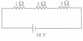
(a) 3 A (b) 6 A (c) 9 A (d) 18 A (a) -
If two or more resistances are connected in such a way that the same potential difference gets applied to each of them, then they are said to be connected in parallel. The. current flowing through the two resistances in parallel is, however, not the same. When we have two or more resistances joined in parallel to one another, then the same current gets additional paths to flow and the overall resistance decreases. The equivalent resistance is given by \(\begin{equation} \frac{1}{R_{p}}=\frac{1}{R_{1}}+\frac{1}{R_{2}}+\frac{1}{R_{3}} \end{equation}\)
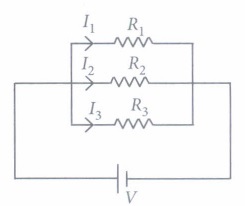
(i) Three resistances, 2 \(\begin{equation} \Omega \end{equation}\) , 6 \(\begin{equation} \Omega \end{equation}\) and 8 \(\begin{equation} \Omega \end{equation}\) are connected in parallel, then the equivalent resistance is
(a) less than 6 \(\begin{equation} \Omega \end{equation}\) but more than 2 \(\begin{equation} \Omega \end{equation}\)
(b) less than 8 \(\begin{equation} \Omega \end{equation}\) but more than 6 \(\begin{equation} \Omega \end{equation}\)
(c) less than 2 \(\begin{equation} \Omega \end{equation}\)
(d) more than 8 \(\begin{equation} \Omega \end{equation}\)
(ii) A wire of resistance 12 \(\begin{equation} \Omega \end{equation}\) is cut into three equal pieces and then twisted their ends together, the equivalent resistance is(a) \(\begin{equation} \frac{3}{8} \Omega \end{equation}\) (b) \(\begin{equation} \frac{4}{3} \Omega \end{equation}\) (c) \(\begin{equation} \frac{3}{4} \Omega \end{equation}\) (d) \(\begin{equation} \frac{5}{6} \Omega \end{equation}\) (iii) Three resistances are connected as shown. The equivalent resistance between A and B is
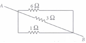
(a) \(\begin{equation} \frac{2}{3} \Omega \end{equation}\) (b) \(\begin{equation} \frac{3}{2} \Omega \end{equation}\) (c) \(\begin{equation} \frac{4}{3} \Omega \end{equation}\) (d) \(\begin{equation} \frac{3}{4} \Omega \end{equation}\) (iv) Which of the following relation is correct?
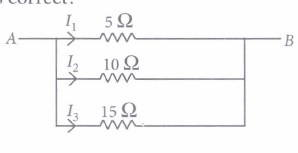
(a) I1 = 2I2 = 3I3 (b) I1 = 4I2 = 3I3 (c) 2I1 = I2 = 3I3 (d) 3I1 = 2I2 = I3 (v) Find the current in each resistance.
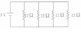
(a) 1 A (b) 2 A (c) 3 A (d) 0.25 A (a) -
Several resistors may be combined to form a network. The combination should have two end points to connect it with a battery or other circuit elements. When the resistances are connected in series, the current in each resistance is same but the potential difference is different in each resistor. When the resistances are connected in parallel, the voltage drop across each resistance is same but the current is different in each resistor.
(i) The household circuits are connected in(a) series combination (b) parallel combination (c) both (a) and (b) (d) none of these (ii) The two wires of each of resistance R, initially connected in series and then in parallel. In the graph it shows the resistance in series and in parallel. Which of the following is correct?
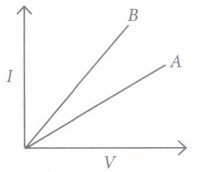
(a) A denotes parallel combination.
(b) B denotes series combination.
(c) A denotes series combination and B denotes parallel combination.
(d) None of these.
(iii) The equivalent resistance of r1 and r2, when connected in series is R1 and when they are connected in parallel is R2. Then the ratio is(a) \(\begin{equation} \frac{r_{1}}{r_{2}} \end{equation}\) (b) \(\begin{equation} \frac{r_{1}+r_{2}}{r_{1} r_{2}} \end{equation}\) (c) \(\begin{equation} \frac{\left(r_{1}+r_{2}\right)^{2}}{r_{1} r_{2}} \end{equation}\) (d) \(\begin{equation} \frac{r_{1} r_{2}}{2 r_{1}+2 r_{2}} \end{equation}\) (iv) The equivalent resistance between A and B is
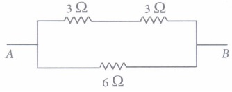
(a) 6 \(\begin{equation} \Omega \end{equation}\) (b) 9 \(\begin{equation} \Omega \end{equation}\) (c) 3 \(\begin{equation} \Omega \end{equation}\) (d) 12 \(\begin{equation} \Omega \end{equation}\) (v) Two resistances 10 \(\begin{equation} \Omega \end{equation}\) and 3 \(\begin{equation} \Omega \end{equation}\)are connected in parallel across a battery. If there is a current of 0.2 A in 10 .Q resistor, the voltage supplied by battery is
(a) 2 V (b) 4 V (c) 1 V (d) 8 V (a) -
The heating effect of current is obtained by transformation of electrical energy in heat energy. Just as mechanical energy used to overcome friction is covered into heat, in the same way, electrical energy is converted into heat energy when an electric current flows through a resistance wire. The heat produced in a conductor, when a current flows through it is found to depend directly on (a) strength of current (b) resistance of the conductor (c) time for which the current flows.
The mathematical expression is given by H = I2Rt.
The electrical fuse, electrical heater, electric iron, electric geyser etc. all are based on the heating effect of current.
(i) What are the properties of heating element?
(a) High resistance, high melting point
(b) Low resistance, high melting point
(c) Low resistance, high melting point
(d) Low resistance, low melting point.
(ii) What are the properties of electric fuse?
(a) Low resistance, low melting point
(b) High resistance, high melting point.
(c) High resistance, low melting point
(d) Low resistance, high melting point
(iii) When the current is doubled in a heating device and time is halved, the heat energy produced is(a) doubled (b) halved (c) four times (d) one fourth times (iv) A fuse wire melts at 5 A. It is is desired that the fuse wire of same material melt at 10 A. The new radius of the wire is
(a) 4 times (b) 2 times (c) \(\begin{equation} \frac{1}{2} \text { times } \end{equation}\) (d) \(\begin{equation} \frac{1}{4} \text { times } \end{equation}\) (v) When a current of 0.5 A passes through a conductor for 5 min and the resistance of conductor is 10 \(\begin{equation} \Omega \end{equation}\), the amount of heat produced is
(a) 250 J (b) 5000J (c) 750J (d) 1000J (a) -
The electrical energy consumed by an electrical appliance is given by the product of its power rating and the time for which it is used. The SI unit of electrical energy is Joule. Actually, Joule represents a very small quantity of energy and therefore it is inconvenient to use where a large quantity of energy is involved. So for commercial purposes we use a bigger unit of electrical energy which is called kilowatt hour. 1 kilowatt-hour is equal to 3.6 x 10⁶ joules of electrical energy.
(i) The energy dissipated by the heater is E. When the time of operating the heater is doubled, the energy dissipated is(a) doubled (b) half (c) remains same (d) four times (ii) The power of a lamp is 60 W The energy consumed in 1 minute is
(a) 360J (b) 36J (c) 3600J (d) 3.6 J (iii) The electrical refrigerator rated 400 W operates 8 hours a day. The cost of electrical energy is \(\begin{equation} ₹ \end{equation}\)5 per kWh. Find the cost of running the refrigerator for one day?
(a) \(\begin{equation} ₹ \end{equation}\)32 (b) \(\begin{equation} ₹ \end{equation}\)16 (c) \(\begin{equation} ₹ \end{equation}\)8 (d) \(\begin{equation} ₹ \end{equation}\)4 (iv) Calculate the energy transformed by a 5 A current flowing through a resistor of 2 \(\begin{equation} \Omega \end{equation}\) for 30 minutes?
(a) 90 kJ (b) 80 kJ (c) 60 kJ (d) 40 kJ (v) Which of the following is correct?
(a) 1 watt hour = 3600 J
(b) lkWh = 36x106J
(c) Energy (in kWh) = power (in W) x time (in hr)
(d) \(\begin{equation} \text { Energy (in kWh) }=\frac{V(\text { volt }) \times I(\text { ampere }) \times t(\text { sec })}{1000} \end{equation}\)(a) -
Shyam made one circuit for his Physics. He used five resistances: two 3Ω, one 1Ω, one 6Ω, one 3.6 Ω and a battery of 4.5 V. The circuit diagram is given below:
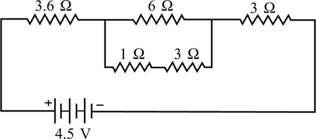
(i) Total resistance of parallel combination is :
(a) 2.4 Ω (b) 3 Ω (c) 6 Ω (d) 2 Ω
(ii) Equivalent resistance of total circuit is :
(a) 5 Ω (b) 9 Ω (c) 11 Ω (d) 13 Ω
(iii) Total current in the circuit is :
(a) 2 A (b) 4.5 A (c) 0.5 A (d) 10 A
(iv) Current in 6 ohm resistance is
(a) 0.3 A (b) 0.2 A (c) 4 A (d) 6 A
(v) Potential across 3.6 ohm resistance will be :
(a) 1.8 V (b) 2.6 V (c) 9 V (d) 4.5 V(a) -
In household electric circuits, the mains supply is delivered to our homes using three core cable as shown here. The cable consists of three wires, live wire, neutral wire and earth wire. The live wire is at potential difference of 220 V for the domestic supply and the potential difference between live and neutral wire is 220 volts. The live wire is connected to electric meter through a fuse or a circuit breaker of higher rating. The neutral wire is connected directly to the electric meter.
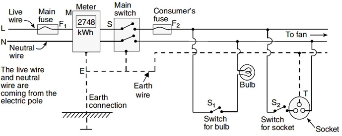
(i) Potential difference between live and neutral wire is
(a) 1000 V (b) 100 V (c) 500 V (d) 220 V
(ii) Switches are connected in household circuit with which wire?
(a) Earth wire (b) Neutral wire (c) Live wire (d) None of these
(iii) What is usual current rating of the fuse wire in the line if electric iron, geysers, room heater etc. are in use?
(a) 15 A (b) 5 A (c) 10 A (d) 25 A
(iv) For all electrical appliances which property of circuit is recommended?
(a) Earthing (b) Neutralising
(c) Connecting with fuse (d) None of these
(v) Home circuit is connected in parallel because
(a) in parallel circuit resistance is maximum
(b) in parallel circuit, if one device is damaged, then it does not affect other devices
(c) both of these
(d) none of these(a) -
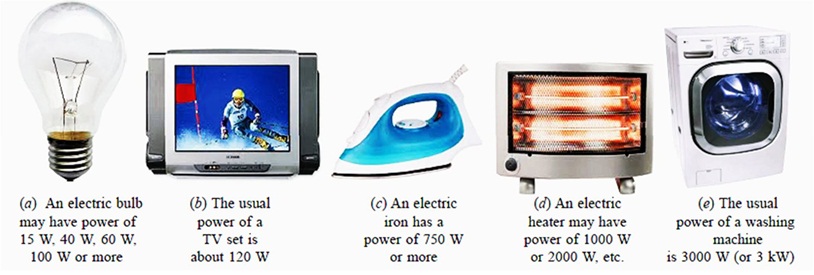
Every electrical appliance like an electric bulb, radio or fan has a label or engraved plate on it which tells us the voltage (to be applied) and the electrical power consumed by it. The power rating of an electrical appliance tells us the rate at which electrical energy is consumed by the appliance. For example, a power rating of 100 watts on the bulb means that it will consume electrical energy at the rate of 100 joules per second. If we know the power P and voltage V of an electrical appliance, then we can very easily find out the current I drawn by it. This can be done by using the formula: P = V x I.
(i) Which of the following does not represent electrical power in a circuit?
(a) I²R (b) IR² (c) VI (d)V²/R
(ii) An electric bulb is rated 220 V and 100 W. What is the resistance of the bulb?
(a) 448 Ω (b) 488 Ω (c) 484 Ω (d) 482 Ω
(iii) When the bulb in (ii) is operated on 110 V, the power consumed will be :
(a) 100 W (b) 75 W (c) 50 W (d) 25 W
(iv) The commercial unit of energy is :
(a) watt (b) watt-hour (c) kilowatt-hour (d) kilo-joule
(v) What will be the current drawn by an electric bulb of 40 W when it is connected to a source of 220 V?
(a) 0.15 A (b) 0.18 A (c) 0.20 A (d) 0.24 A(a) -
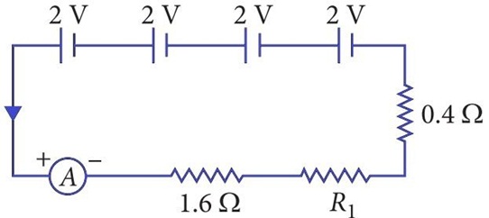
A student is making his Physics project. He purchased four cells, an ammeter and three resistors for his project. In his project, Four cells each of emf 2 V are connected in series. The combination in series is joined to an ammeter of negligible resistance, a 1.6 Ω resistor, a 0.4 Ω resistor and unknown resistor R1 as shown in figure. The current in the circuit is 2 A.
(i) What is the value of R1?
(a) 1 Ω (b) 2 Ω (c) 4 Ω (d) 6 Ω
(ii) Find the value of potential difference across R1.
(a) 4 V (b) 2 V (c) 8 V (d) 12 V
(iii) Calculate the total resistance of the circuit.
(a) 3.75 Ω (b) 3.125 Ω (c) 3.5 Ω (d) 4 Ω
(iv) Find the value of current across resistor R1.
(a) 1.33 A (b) 0.25 A (c) 2 A (d) 3 A
(v) If one of the cell is removed, the current through 1.6 Ω will be
(a) 2 A (b) 1.5 A (c) 6 A (d) 0.25 A(a) -
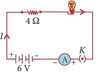
An electric lamp is a device that produces visible light from electric current. It is the most common form of artificial lighting and is essential to modern society. An electric lamp of resistance 20 Ω and a conductor of resistance 4 Ω are connected to a 6 V battery as shown in the circuit.
(i) Find the total resistance of the circuit.
(a) 20 Ω (b) 4 Ω (c) 24 Ω (d) 12 Ω
(ii) Find the current through the circuit, is
(a) 0.25 A (b) 0.50 A (c) 1 A (d) 4 A
(iii) Find the potential difference across the electric lamp.
(a) 5 V (b) 10 V (c) 15 V (d) 20 V
(iv) Find the potential difference across conductor.
(a) 0 V (b) 0.25 V (c) 0.5 V (d) 1 V
(v) Calculate power of the lamp.
(a) 2.0 W (b) 1.25 W (c) 0.25 W (d) 6.25 W(a) -
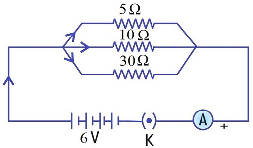
Aditya decided to complete his Physics Project. He purchased three resistors 5 Ω, 10 Ω and 30 Ω from the shop. Later he purchased a 6 V battery, switch (which works as key) and an ammeter to complete his circuit as shown below:
(i) Find the current through 5 Ω.
(a) 1.2 A (b) 1.5 A (c) 1 A (d) 2 A
(ii) Find the current through 10 Ω.
(a) 0.6 A (b) 0.2 A (c) 1 A (d) 0.5 A
(iii) Find the current through 30 Ω.
(a) 0.6 A (b) 0.2 A (c) 1 A (d) 0.5 A
(iv) Find the total current in the circuit.
(a) 1.2 A (b) 1.5 A (c) 1 A (d) 2 A
(v) Find the total resistance of the circuit.
(a) 2 Ω (b) 4 Ω (c) 3 Ω (d) 5 Ω(a) -
Aditya decided to complete his Physics Project. He purchased three resistors 4 Ω, 8 Ω and 8 Ω from the shop. Later he purchased a 8 V battery, switch (which works as key) and two ammeters to complete his circuit as shown below:
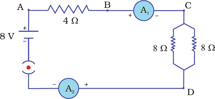
(i) Find the effective resistance of two 8 resistors in the combination
(a) 2 Ω (b) 4 Ω (c) 3 Ω (d) 5 Ω
(ii) Find the current flowing through the circuit.
(a) 1.2 A (b) 1.5 A (c) 1 A (d) 2 A
(iii) Find the potential difference across 4 Ω resistance.
(a) 2 V (b) 3 V (c) 4 V (d) 5 V
(iv) Find the power dissipated in 4 Ω resistor
(a) 2 W (b) 3 W (c) 4 W (d) 5 W
(v) Find the difference in ammeter readings.
(a) 1 (b) 2 (c) 3 (d) No difference(a)
Case Study
*****************************************
Answers
Electricity Case Study Questions With Answer Key Answer Keys
-
(i) (a): q = 2 C, t= 100 ms = 0.1 s
\(\begin{equation} I=\frac{q}{t}=\frac{2}{0.1}=20 \mathrm{~A} \text { . } \end{equation}\)
(ii) (d)
(iii) (b): W = 100 J, q = 20 C
\(\begin{equation} V=\frac{W}{q}=\frac{100}{20}=5 \mathrm{~V} \end{equation}\)
(iv) (c): I = 1 A, t = 1 s
q = It = 1 x 1 = 1C
\(\begin{equation} n=\frac{q}{e}=\frac{1}{1.6 \times 10^{-19}}=6.25 \times 10^{18} \end{equation}\)
(v) (c): \(\begin{equation} V=\frac{W}{q}=\frac{W}{I t} \end{equation}\) -
(i)(a): V = IR
So, V' \(\rightarrow\) 2 V, R' \(\rightarrow\) 2R
\(\begin{equation} I^{\prime}=\frac{2 V}{2 R}=I \end{equation}\)
(ii) (b): V \(\begin{equation} \propto \end{equation}\) I. So, the graph is a straight line and passing through origin.
(iii) (b): Slope of V-I graph = \(\begin{equation} \frac{I}{V}=\frac{1}{R} \text { . } \end{equation}\)
(iv) (c): Given: V = 9 V, 1= 0.1 A
\(\begin{equation} R=\frac{V}{I}=\frac{9}{0.1}=90 \Omega \end{equation}\)
(v) (c): On increasing the voltage, the resistance remain same, so current will increase . -
(i) (b): The electrical wire should have low resistance.
(ii) (b): More is the temperature, more will be the resistance. The resistance of A is more, so temperature of A is more.
(iii) (c): \(\begin{equation} R_{1}=\rho \frac{L}{A}, R_{2}=\rho \frac{2 L}{A / 2} \end{equation}\)
(iv) (a): In summers, temperature is more, so resistance is more.
(v) (a): \(\begin{equation} R^{\prime}=\frac{R}{5}=\frac{20}{5}=4 \Omega \end{equation}\) -
(i) (b): In series combination, the total voltage is equal to the sum of voltage drop across each resistance.
(ii) (b): Rs = R1 + R2 + R3
So, Rs = R + R + R = 3R
(iii) (a): Resistance of each wire = 20/4 = 5 \(\begin{equation} \Omega \end{equation}\)
Equivalent resistance in series
Rs = 5 + 5 + 5 + 5 = 20 \(\begin{equation} \Omega \end{equation}\)
(iv) (a): All are in series, Rs = 5R= 5 x 2 = 10\(\begin{equation} \Omega \end{equation}\)
(v) (a): Rs = 1 + 2 + 3 = 6 \(\begin{equation} \Omega \end{equation}\)
\(\begin{equation} I=\frac{18}{6}=3 \mathrm{~A} \end{equation}\) -
(i) (c) :The equivalent resistance in the parallel combination is lesser than the least value, of the individual resistance.
(ii) (b): Resistance of each piece \(\begin{equation} =\frac{12}{3}=4 \Omega \end{equation}\)
\(\begin{equation} \frac{1}{R_{P}}=\frac{1}{4}+\frac{1}{4}+\frac{1}{4}=\frac{3}{4} \Rightarrow R_{p}=\frac{4}{3} \Omega \end{equation}\)
(iii) (a): All the three resistors are in parallel.
\(\begin{equation} \frac{1}{R_{p}}=\frac{1}{6}+\frac{1}{3}+\frac{1}{1}=\frac{1+2+6}{6}=\frac{9}{6} \end{equation}\)
\(\begin{equation} R_{P}=\frac{6}{9}=\frac{2}{3} \Omega \end{equation}\)
(iv) (a): Voltage is same across each resistance.
So, I1 x 5 = I2 X 10 = 15 x I3
I1 = 2I2 = 3I3
(v) (d): All are in parallel.
\(\begin{equation} \begin{array}{l} \frac{1}{R_{p}}=\frac{1}{12} \times 4=\frac{1}{3} \Rightarrow R_{p}=3 \Omega \\ I=\frac{3}{3}=1 \mathrm{~A} \end{array} \end{equation}\)
So, current in each resistor \(\begin{equation} I^{\prime}=\frac{3}{12}=\frac{1}{4} \mathrm{~A} \end{equation}\) -
(i) (b)
(ii) (c): In series combination, resistance is maximum and in parallel combination, resistance is mcm.
(iii) (c) : R1 = r1 + r2
\(\begin{equation} \begin{array}{l} R_{2}=\frac{r_{1} r_{2}}{r_{1}+r_{2}} \\ \frac{R_{1}}{R_{2}}=\frac{\left(r_{1}+r_{2}\right)^{2}}{r_{1} r_{2}} \end{array} \end{equation}\)
(iv) (c): In the given circuit, 3 \(\begin{equation} \Omega \end{equation}\) resistors are in series. RS = 3 + 3 = 6 \(\begin{equation} \Omega \end{equation}\)
Now, RS and 6 \(\begin{equation} \Omega \end{equation}\) are parallel.
\(\begin{equation} \frac{1}{R_{p}}=\frac{1}{6}+\frac{1}{6}=\frac{2}{6}=\frac{1}{3} \Rightarrow R_{p}=3 \Omega \end{equation}\)
(v) (a): V = 0.2 x 10= 2 V
So, total voltage supplied is same as 2 V. -
(i) (b)
(ii) (c)
(iii) (a): Given: H = I2Rt
\(\begin{equation} \mathrm{So}, H^{\prime}=(2 I)^{2} \cdot \frac{R}{2} t=2 H \end{equation}\)
(iv) (b): Given: 1= 5 A, resistance = R. Let r be the new radius.
Now,H=I2Rt
Also H' = I'2 R' t
From (i) and (ii), \(\begin{equation} 5^{2} \times \rho \frac{L}{\pi r^{2}} t=10^{2} \times \rho \frac{L}{\pi r^{\prime 2}} \cdot t \end{equation}\)
\(\begin{equation} \frac{25}{r^{2}}=\frac{100}{r^{\prime 2}} \Rightarrow \frac{r^{\prime}}{r}=2 \Rightarrow r^{\prime}=2 r \end{equation}\)
(v) (c): Given: \(\begin{equation} I=0.5 \mathrm{~A}, R=10 \Omega, t=5 \mathrm{~min} \end{equation}\)
\(\begin{equation} \begin{array}{l} H=I^{2} R t=0.5 \times 0.5 \times 10 \times 5 \times 60 \\ H=750 \mathrm{~J} \end{array} \end{equation}\) -
(i) (a): \(\begin{equation} E \propto t \end{equation}\)
(ii) (c): Given: P = 60W, t = 1 min
E = 60 x 1 x 60 = 3600J
(iii) (b): Given: P = 400\(\begin{equation} \Omega \end{equation}\), t = 8 hour
E = 400 x 8 = 3200Wh = 3.2kWh
Cost = 3.2 x 5 = \(\begin{equation} ₹ \end{equation}\) 16
(iv) (a): Given: I= 5 A, R = 2 \(\begin{equation} \Omega \end{equation}\) , t = 30 min
E = I2Rt = 5 x 5 x 2 x 30 x 60
E = 90000J = 90 kJ
(v) (a): 1watt hr = 3600J -
(i) (a) 2.4 Ω
(ii) (b) 9 Ω
(iii) (c) 0.5 A
(iv) (b) 0.2 A
(v) (a) 1.8 V -
(i) (d) 220 V
The potential different between live and neutral wire is 220 Volts
(ii) (c) Live wire
Switches are connected in the live wire because when the switch is in the off position, no point of the connected electrical appliance will be at higher potential (220 V).
(iii) (a) 15 A
A fuse of rating 15 A is usually used for appliance electric iron, geysers and room heater etc.
(iv) (a) Earthing
The earthing of any electrical appliance is done to protect the user from any accidental electrical shock due to leakage of current.
(v) (b) in parallel circuit if one device is damaged, then it does not affect other devices. -
(i) (b) IR²
(ii) (c) 484 Ω
(iii) (d) 25 W
(iv) (c) kilowatt-hour
(v) (b) 0.18 A -
(i) (b) 2 Ω
(ii) (a) 4 V
(iii) (d) 4 Ω
(iv) (c) 2 A
(v) (b) 1.5 A -
(i) (c) 24 Ω
(ii) (a) 0.25 A
(iii) (a) 5 V
(iv) (d) 1 V
(v) (b) 1.25 W -
(i) (c) 24 Ω
(ii) (a) 0.25 A
(iii) (a) 5 V
(iv) (d) 1 V
(v) (b) 1.25 W -
(i) (b) 4 Ω
(ii) (c) 1 A
(iii) (c) 4 V
(iv) (c) 4 W
(v) (d) No difference
Case Study


