


Class 12th Physics - Current Electricity Case Study Questions and Answers 2022 - 2023
QB365 provides a detailed and simple solution for every Possible Case Study Questions in Class 12th Physics Subject - Current Electricity, CBSE. It will help Students to get more practice questions, Students can Practice these question papers in addition to score best marks.
QB365 - Question Bank Software
Current Electricity Case Study Questions With Answer Key
12th Standard CBSE
-
Reg.No. :
Physics
-
The flow of charge in a particular direction constitutes the electric current. Current is measured in Ampere. Quantitatively, electric current in a conductor across an area held perpendicular to the direction of flow of charge is defined as the amount of charge is flowing across that area per unit time.
Current density at a point in a conductor is the ratio of the current at that point in the conductor to the area of cross section of the conductor of that point.
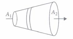
The given figure shows a steady current flows in a metallic conductor of non uniform cross section. Current density depends inversely on area, so, here \(J_{1}>J_{2}, \text { as } A_{1}
(i) What is the current flowing through a conductor, if one million electrons are crossing in one millisecond through a cross-section of it ?(a) 2.5 x 10⁻¹⁰ A (b) 1.6 x 10⁻¹⁰ A (c) 7.5 X 10⁻⁹ A (d) 8.2 x 10⁻¹¹ A (ii) SI unit of electric current is
(a) Cs (b) Ns-2 (c) Cs-1 C-1s-1 (iii) A steady current flows in a metallic conductor of non-uniform cross-section. Which of these quantities is constant along the conductor?
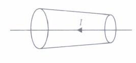
(a) Electric field (b) Drift velocity (c) Current (d) Current density (iv) A constant current I is flowing along the length of a conductor of variable cross-section as shown in the figure. The quantity which does not depend upon the area of cross-section is
(a) electron density (b) current density (c) drift velocity (d) electric field (v) When a current of 40 A flows through a conductor of area 10 m2, then the current density is
(a) 4 A/m2 (b) 1 A/m2 (c) 2 A/m2 (d) 8 A/m2 -
According to Ohm's law, the current flowing through a conductor is directly proportional to the potential difference across the ends of the conductor i.e \(I \propto V \Rightarrow \frac{V}{I}=R\) where R is resistance of the conductor Electrical resistance of a conductor is the obstruction posed by the conductor to the flow of electric current through it. It depends upon length, area of cross-section, nature of material and temperature of the conductor We can write \(R \propto \frac{l}{A} \text { or } R=\rho \frac{l}{A}\) where \(\rho\) is electrical resistivity of the material of the conductor.
(i) Dimensions of electric resistance is\(\text { (a) }\left[\mathrm{ML}^{2} \mathrm{~T}^{-2} \mathrm{~A}^{-2}\right]\) \(\text { (b) }\left[M L^{2} T^{-3} A^{-2}\right]\) \(\text { (c) }\left[\mathrm{M}^{-1} \mathrm{~L}^{-2} \mathrm{~T}^{-1} \mathrm{~A}\right]\) \(\text { (d) }\left[M^{-1} L^{2} T^{2} A^{-1}\right]\) (ii) If \(1 \mu \mathrm{A}\) current flows through a conductor when potential difference of2 volt is applied across its ends, then the resistance of the conductor is
\(\text { (a) } 2 \times 10^{6} \Omega\) \(\text { (b) } 3 \times 10^{5} \Omega\) \(\text { (c) } 1.5 \times 10^{5} \Omega\) \(\text { (d) } 5 \times 10^{7} \Omega\) (iii) Specific resistance of a wire depends upon
(a) length (b) cross-sectional area (c) mass (d) none of these (iv) The slope of the graph between potential difference and current through a conductor is
(a) a straight line (b) curve (c) first curve then straight line (d) first straight line then curve (v) The resistivity of the material of a wire 1.0 m long, 0.4 mm in diameter and having a resistance of 2.0 ohm is
\(\text { (a) } 1.57 \times 10^{-6} \Omega \mathrm{m}\) \(\text { (b) } 5.25 \times 10^{-7} \Omega \mathrm{m}\) \(\text { (c) } 7.12 \times 10^{-5} \Omega \mathrm{m}\) \(\text { (d) } 2.55 \times 10^{-7} \Omega \mathrm{m}\) -
The resistance of a conductor at temperature toC is given by Rt = Ro (1 + \(\alpha\)t)
where Rt is the resistance at toC, Ro is the resistance at 0oC and \(\alpha\) is the characteristics constants of the material of the conductor.
Over a limited range of temperatures, that is not too large. The resistivity of a metallic conductor is approximately given by \(\rho_{t}=\rho_{0}(1+\alpha t)\).
where \(\alpha\) is the temperature coefficient of resistivity. Its unit is \(\mathrm{K}^{-1} \text {or }{ }^{\circ} \mathrm{C}^{-1}\)
For metals, \(\alpha\) is positive i.e., resistance increases with rise in temperature.
For insulators and semiconductors, \(\alpha\) is negative i.e., resistance decreases with rise in temperature.
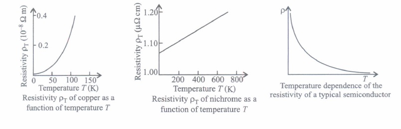
(i) Fractional increase in resistivity per unit increase in temperature is defined as(a) resistivity (b) temperature coefficient of resistivity (c) conductivity (d) drift velocity (ii) The material whose resistivity is insensitive to temperature is
(a) silicon (b) copper (c) silver (d) nichrome (iii) The temperature coefficient of the resistance of a wire is 0.00125 per oC. At 300 K its resistance is 1 ohm. The resistance of wire will be 2 ohms at
(a) 1154 K (b) 1100 K (c) 1400 K (d) 1127 K (iv) The temperature coefficient of resistance of an alloy used for making resistors is
(a) small and positive (b) small and negative (c) large and positive (d) large and negative (v) For a metallic wire, the ratio V/I (V = applied potential difference and I = current flowing) is
(a) independent of temperature (b) increases as the temperature rises (c) decreases as the temperature rises (d) increases or decreases as temperature rises depending upon the metal -
Emf of a cell is the maximum potential difference between two electrodes of the cell when no current is drawn from the cell. Internal resistance is the resistance offered by the electrolyte of a cell when the electric current flows through it. The internal resistance of a cell depends upon the following factors;
(i) distance between the electrodes
(ii) nature and temperature of the electrolyte
(iii) nature of electrodes
(iv) area of electrodes.
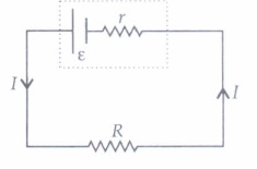
For a freshly prepared cell, the value of internal resistance is generally low and goes on increasing as the cell is put to more and more use. The potential difference between the two electrodes of a cell in a closed circuit is called terminal potential difference and its value is always less than the emf of the cell in a closed circuit. It can be written as V = E - Jr.
(i) The terminal potential difference of two electrodes of a cell is equal to emf of the cell when\(\text { (a) } I \neq 0\) (b) I=0 (c) both (a) and (b) (d) neither (a)nor (b) (ii) A cell of emf E and internal resistance r gives a current of 0.5 A with an external resistance of \(12 \Omega\) and a current of 0.25 A with an external resistance of \(25 \Omega\) .What is the value of internal resistance of the cell?
\(\text { (a) } 5 \Omega\) \(\text { (b) } 1 \Omega\) \(\text { (c) } 7 \Omega\) \(\text { (d) } 3 \Omega\) (iii) Choose the wrong statement.
(a) Potential difference across the terminals of a cell in a closed circuit is always less than its emf. (b) Internal resistance of a cell decrease with the decrease in temperature of the electrolyte. (c) Potential difference versus current graph for a cell is a straight line with a -ve slope (d) Terminal potential difference of the cell when it is being charged is given as V = E + Ir. (iv) An external resistance R is connected to a cell of internal resistance r, the maximum current flows in the external resistance, when
(a) R = r (b) R < r (c) R> r (d) R=l/r (v) IF external resistance connected to a cell has been increased to 5 times, the potential difference across the terminals of the cell increases from 10 V to 30 V. Then, the emf of the cell is
(a) 30 V (b) 60V (c) 50 V (d) 40 V -
Metals have a large number of free electrons nearly 1028 per cubic metre. In the absence of electric field, average terminal speed of the electrons in random motion at room temperature is of the order of 105 m s-1 When a potential difference V is applied across the two ends of a given conductor, the free electrons in the conductor experiences a force and are accelerated towards the positive end of the conductor. On their way, they suffer frequent collisions with the ions/atoms of the conductor and lose their gained kinetic energy. After each collision, the free electrons are again accelerated due to electric field, towards the positive end of the conductor and lose their gained kinetic energy in the next collision with the ions/atoms of the conductor. The average speed of the free electrons with which they drift towards the positive end of the conductor under the effect of applied electric field is called drift speed of the electrons.
(i) Magnitude of drift velocity per unit electric field is(a) current density (b) current (c) resistivity (d) mobility (ii) The drift speed of the electrons depends on
(a) dimensions of the conductor (b) number density of free electrons in the conductor (c) both (a) and (b) (d) neither (a) nor (b) (iii) We are able to obtain fairly large currents in a conductor because
(a) the electron drift speed is usually very large (b) the number density of free electrons is very high and this can compensate for the low values of the 6 electron drift speed and he very small magnitude of the electron charge (c) the number density of free electrons as well as the electron drift speeds are very large and these compensate for the very small magnitude of the electron charge (d) the very small magnitude of the electron charge has to be divided by the still smaller product of the number density and drift speed to get the electric current (iv) Drift speed of electrons in a conductor is very small i.e., i = 10-4 m s-1. The Electric bulb glows immediately. When the switch is closed because
(a) drift velocity of electron increases when switch is closed (b) electrons are accelerated towards the negative end of the conductor (c) the drifting of electrons takes place at the entire length of the conductor (d) the electrons of conductor move towards the positive end and protons of conductor move towards negative end of the conductor (v) The number density offree electrons in a copper conductor is 8.5 x 1028 m-3. How long does an electron take to drift from one end of a wire 3.0 m long to its other end? The area of cross-section of the wire is 2.0 x 10⁻⁶m2 and it is carrying a current of 3.0 A.
(a) 8.1 x 10⁴ s (b) 2.7 x 10⁴ s (c) 9 x 10³ s (d) 3 x 10³ S -
A single cell provides a feeble current. In order to get a higher current in a circuit, we often use a combination of cells A combination of cells is called a battery, Cells can be joined in series, parallel or in a mixed way.
Two cells are said to be connected in series when negative terminal of one cell is connected to positive terminal of the other cell and so on. Two cells are said to be connected in parallel if positive terminal of each cell is connected to one point and negative terminal of each cell connected to the other point. In mixed grouping of cells, a certains number of identical cells are joined in series, and all such rows are then connected in parallel with each other.
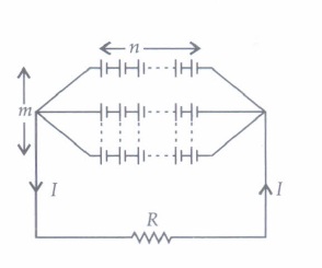
(i) To draw the maximum current from a combination of cells, how should the cells be grouped?(a) Parallel (b) Series (c) Mixed grouping (d) Depends upon the relative values of internal and external resistances (ii) The total emf of the cells when n identical cells each of emf e are connected in parallel is
\(\text { (a) } n \varepsilon\) \(\text { (b) } n^{2} \varepsilon\) (c) E \(\text { d) } \frac{\varepsilon}{n}\) (iii) 4 cells each of emf 2 V and internal resistance of \(1 \Omega\) are connected in parallel to a load resistor of \(2 \Omega\). Then the current through the load resistor is
(a) 2 A (b) 1.5 A (c) 1 A (d) 0.888 A (iv) If two cells out of n number of cells each of internal resistance 'r' are wrongly connected in series, then total resistance of the cell is
(a) 2nr (b) nr - 4r (c) nr (d) r (v) Two identical non-ideal batteries are connected in parallel. Consider the following statements.
(i). The equivalent emf is smaller than either of the two emfs.
(ii) The equivalent internal resistance is smaller than either of the two internal resistances(a) Both (i) and (ii) are correct. (b) (i) is correct but (ii) is wrong (c) (ii) is correct but (i) is wrong. (d) Both (i) and (ii) are wrong. -
In 1942, a German physicist Kirchhoff extended Ohm's law to complicated circuits and gave two laws, which enable us to determine current in any part of such a circuit. According to Kirchhoff's first rule, the algebraic sum of the currents meeting at a junction in a closed electric circuit is zero. The current flowing in a conductor towards the junction is taken as positive and the current flowing away from the junction is taken as negative. According to Kirchhoff's second rule, in a closed loop, the algebraic sum of the emf's and algebraic sum of the products of current and resistance in the various arms of the loop is zero. While traversing a loop, if negative pole of the cell is encountered first, then its emf is negative, otherwise positive.
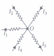
(i) Kirchhoff's Ist law follows(a) law of conservation of energy (b) law of conservation of charge (c) law of conservation of momentum (d) Newton's third law of motion (ii) The value of current I in the given circuit is
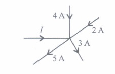
(a) 4.5 A (b) 3.7 A (c) 2.0 A (d) 2.5 A (iii) Kirchhoff's IInd law is based on
(a) law of conservation of momentum of electron (b) law of conservation of charge and energy (c) law of conservation of energy (d) none of these. (iv) Point out the right statements about the validity of Kirchhoff's Junction rule.
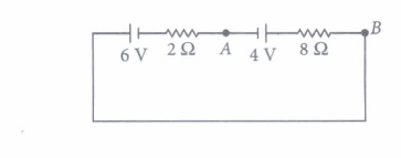
(a) The current flowing towards the junction are taken as positive. (b) The currents flowing away from the junction are taken as negative. (c) bending or reorienting the wire does not change the validity of Kirchhoff's Junction rule (d) All ofthe above (v) Potential difference between A and B in the circuit shown here is
(a) 4 V (b) 5.6 V (c) 2.8 V (d) 6 V -
Wheatstone bridge is an arrangement of four resistances P, Q, Rand S connected as shown in the figure. Their values are so adjusted that the galvanometer G shows no deflection. The bridge is then said to be balanced when this condition is achieved happens. In the setup shown here, the points Band D are at the same potential and it can be shown that \(\frac{P}{Q}=\frac{R}{S}\)
This is called the balancing condition. If any three resistances are known, the fourth can be found.
The practical form of Wheatstone bridge is slide wire bridge or Meter bridge. Using this the unknown resistance can be determined as \(S=\left(\frac{100-l}{l}\right) \times R\) ,where I is the balancing length of the Meter bridge.
(i) In a Wheatstone bridge circuit, \(P=5 \Omega, Q=6 \Omega, R=10 \Omega\) and \(S=5 \Omega\) What is the value of additional resistance to be used in series with S, so that the bridge is balanced?\(\text { (a) } 9 \Omega\) \(\text { (b) } 7 \Omega\) \(\text { (c) } 10 \Omega\) \(\text { (d) } 5 \Omega\) (ii) A Wheatstone bridge consisting of four arms of resistances P, Q, R, S is most sensitive when
(a) all the resistances are equal (b) all the resistances are unequal (c) the resistances P and Q are equal but R > > P and S > > Q (d) the resistances P and Q are equal but R < < P and S < < Q (iii) When a metal conductor connected to left gap of a meter bridge is heated, the balancing point
(a) shifts towards right (b) shifts towards left (c) remains unchanged (d) remains at zero (iv) The percentage error in measuring resistance with a meter bridge can be minimized by adjusting the balancing point close to
(a) 0 (b)·20cm (c) 50cm (d) 80cm (v) In a meter bridge experiment, the ratio ofleft gap resistance to right gap resistance is 2 : 3. The balance point from left is
(a) 20 cm (b) 50 cm (c) 40 cm (d) 60 cm -
Potentiometer is an apparatus used for measuring the emf of a cell or potential difference between two points in an electrical circuit accurately. It is also used to determine the internal resistance of a primary cell. The potentiometer is based on the principle that, if V is the potential difference across any portion of the wire of length 1 and resistance R, then \(V \propto l \text { or } V=k l\) where k is the potential gradient. Thus, potential difference across any portion of potentiometer wire is directly proportional to length of the wire of that portion. The potentiometer wire must be uniform. The resistance of potentiometer wire should be high.
(i) Which one of the following is true about potentiometer?(a) Its sensitivity is low (b) It measures the emf of a cell very accurately (c) It is based on deflection method (d) None of the above (ii) A current of 1.0 mA is flowing through a potentiometer wire of length 4 cm and of resistance \(4 \Omega\) .The potential gradient of the potentiometer wire is
\(\text { (a) } 10^{-3} \mathrm{Vm}^{-1}\) \(\text { (b) } 10^{-5} \mathrm{Vm}^{-2}\) \(\text { (c) } 2 \times 10^{-3} \mathrm{Vm}^{-1}\) \(\text { (d) } 4 \times 10^{-3} \mathrm{Vm}^{-1}\) (iii) Sensitivity of a potentiometer can be increased by
(a) decreasing potential gradient along the wire (b) increasing potential gradient along the wire (c) decreasing current through the wire (d) increasing current through the wire (iv) A potentiometer is an accurate and versatile device to make electrical measurements of EMF because the method involves
(a) potential gradients (b) a condition of no current flow through the galvanometer (c) a combination of cells, galvanometer and resistances (d) cells (v) In a potentiometer experiment, the balancing length is 8 m, when the two cells El and E2 are joined in series. When the two cells are connected in opposition the balancing length is 4 m. The ratio of the e. m. f. of two cells (El/E2) is
(a) 1: 2 (b) 2: 1 (c) 1: 3 (d) 3: 1 -
Whenever an electric current is passed through a conductor, it becomes hot after some time. The phenomenon of the production of heat in a resistor by the flow of an electric current through it is called heating effect of current or Joule heating. Thus, the electrical energy supplied by the source of emf is converted into heat. In purely resistive circuit, the energy expended by the source entirely appears as heat. But if the circuit has an active element like a motor, then a part of the energy supplied by the source goes to do useful work and the rest appears as heat. Joule's law of heating form the basis of various electrical appliances such as electric bulb, electric furnace,
electric press etc.
(i) Which of the following is a correct statement?(a) Heat produced in a conductor is independent of the current flowing (b) Heat produced in a conductor varies inversely as the current flowing (c) Heat produced in a conductor varies directly as the square of the current flowing (d) Heat produced in a conductor varies inversely as the square of the current flowing (ii) If the coil of a heater is cut to half, what would happen to heat produced?
(a) Doubled (b) Halved (c) Remains same (d) Becomes four times (iii) A 25 Wand 100 Ware joined in series and connected to the mains. Which bulbs will glow brighter?
(a) 100W (b) 25 W (c) both bulbs will glow brighter (d) none will glow brighter (iv) A rigid container with thermally insulated wall contains a coil of resistance \(100 \Omega\) carrying current 1A. Change in its internal' energy after 5 min will be
(a) 0 kJ (b) 10 kJ (c) 20 kJ (d) 30 kJ (v) The heat emitted by a bulb of 1.90W in 1 min is
(a) 100 J (b) 1000 J (c) 600 J (d) 6000 J -
When a conductor does not have a current through it, its conduction electrons move randomly, with no net motion in any direction. When the conductor does have a current through it, these electrons actually still move randomly, but now they tend to drift with a drift speed V\(\alpha\) in the direction opposite to the applied electric field that causes current. The drift speed is very small as compared to the speeds in the random motion. For example, in the copper r conductors of household wiring, electron drift speeds are perhaps 10- 5 ms1 to 10-3 ms-1 where as the random speed is around 106 ms-1 .
(i) The electron drift speed is estimated to be only a few mm S-1 for currents in the range of a few amperes? How is current established almost the instant a circuit is closed?
(ii) The electron drift arises due to the force experienced by electrons in the electric field inside the conductor. But force should cause acceleration. Why do the electrons acquire a steady average drift speed?
(iii) If the electron drift speed is so small, and the electron's charge is small, how can we still obtain large amounts of current in a conductor?
(iv) When electrons drift in a metal from lower to higher potential, does it mean that all the 'free' electrons of the metal are moving in the same direction?
(v) Are the paths of electrons straight lines between successive collisions (with the positive ions of the metal) in the (a) absence of electric field, (b) presence of electric field? -
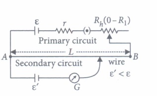
A student while doing experiment connected six wire (600 cm) potentiameter to a cell of emf E, and a key, so that 50 mA current started flowing from A to B. Here A and B are two ends of a potentiameter wire. For a cell of emf 2 V and internal resistance 10 \(\Omega\), he found null point at 500 cm from A. But when he connected voltmeter across the cell, the balancing length is decreased by 10 cm.
(i) What is the potential gradient along the wire?
(ii) Reading of voltmeter is ______
(iii) Determine the resistance of voltmeter.
(iv) Now, instead of a cell, if only voltmeter is connected with one end to point A and another end to sliding contact then plot variation of potential difference against length as sliding contact moves away from A. Which physical quantity will represent slope of this graph? -
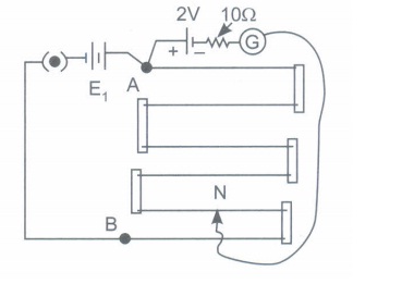
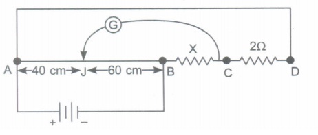
AB is a metre long wire of a potentiometer. On connecting a cell E2 across AC (AC = 60 cm), no current flows from E2 If internal resistance of cell E. is assumed to be negligible, then determine
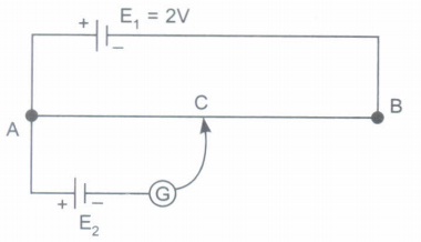
(i) Potential gradient along wire AB.
(ii) EMF of cell E2
(iii) Will balancing point change if E2 has same internal resistance? -
(i) AB is a metre long wire having uniform cross sectional area. An unknown resistance X and a resistance of 2 \(\Omega\) are connected by thick conducting strips. Connect a battery and a galvanometer to measure unknown resistance X using Wheatstone bridge principle.
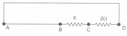
(ii) Assuming all the connections to be correct, if balance point is obtained at 40 cm from point A, then what is the value of resistance X?
(iii) If one more resistance of 6\(\Omega\) is connected in parallel to X, then determine the balancing length. -
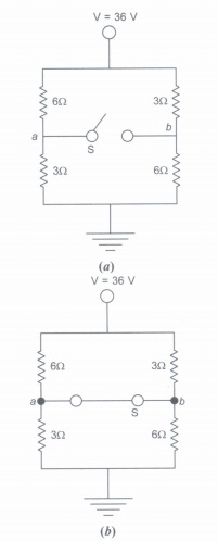
In the figure given below, the battery (or other power supply) is not shown, but it is understood that the point at the top, labeled "36V", is connected to the positive terminal of a 36 V battery having negligible internal resistance, and the "ground" symbol at the bottom to its negative terminal. The circuit is completed through the battery, even though it is not shown on the diagram.
(i) In figure (a) what is the potential difference Va - Vb when switch S is open?
(ii) What is the current through switch S, when it is closed?
-
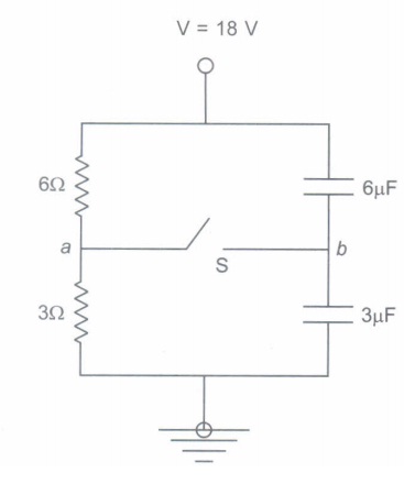
(i) What is the potential difference between points a and b when switch S is open?
(ii) What are the potentials at points a and b when switch is closed?
(iii) How much charge will flow through capacitor of capacitance 6 IlF as soon as the switch S is closed?
Case Study
*****************************************
Answers
Current Electricity Case Study Questions With Answer Key Answer Keys
-
(I) (b): \(q=10^{6} \times 1.6 \times 10^{-19} \mathrm{C}=1.6 \times 10^{-13} \mathrm{C}\)
t = 10-3 s
\(I=\frac{q}{t}=\frac{1.6 \times 10^{-13}}{10^{-3}}=1.6 \times 10^{-10} \mathrm{~A}\)
(ii) (C): C S-1
(iii) (C): The current flowing through a conductor of non-uniform cross-section remain same in the whole of the conductor.
(iv) (a): When a constant current is flowing through a conductor of non-uniform cross-section, electron density does not depend upon the area of cross section, while current density, drift velocity and electric field all vary inversely with area of cross-section.
(v) (a): Given, I = 40 A ;A = 10m2
\(\therefore\) Current density, \(J=\frac{I}{A} \text { or } J=\frac{40}{10}=4 \mathrm{~A} / \mathrm{m}^{2}\) -
(i) (b)
(ii) (a): \(R=\frac{V}{I}=\frac{2}{10^{-6}}=2 \times 10^{6} \Omega\)
(iii) (d): Specific resistance depends upon the nature of material and is independent of mass and dimensions of the material
(iv) (a)
(v) (d): l = 1.0 m; D = 0.4 mm = 4 x 10⁻⁴m
\(R=2 \Omega\)
\(A=\frac{\pi D^{2}}{4}=\frac{\pi \times\left(4 \times 10^{-4}\right)^{2}}{4}=4 \pi \times 10^{-8} \mathrm{~m}^{2}\)
Now, \(\rho=\frac{R A}{l}=\frac{2 \times 4 \pi \times 10^{-8}}{1}=2.55 \times 10^{-7} \Omega \mathrm{m}\) -
(i) (b): Temperature coefficient of resistivity is defined as the fractional increase in resistivity per unit increase in temperature.
(ii) (d): Nichrome (which is an alloy of nickel, iron and chromium) exhibits a very weak dependence of resistivity with temperature.
(iii) (d): Using, \(R_{T}=R_{0}(1+\alpha T)\)
\(\therefore \quad \frac{R_{T_{2}}}{R_{T_{1}}}=\frac{R_{0}\left(1+\alpha T_{2}\right)}{R_{0}\left(1+\alpha T_{1}\right)}=\frac{2}{1}=\frac{\left(1+\alpha T_{2}\right)}{(1+\alpha \times 300)}\)
\(\Rightarrow \quad 2+\alpha \times 600=1+\alpha T_{2}\)
\(\Rightarrow \quad 1=\alpha\left(T_{2}-600\right) \Rightarrow \frac{1}{0.00125}=\left(T_{2}-600\right)\)
\(\Rightarrow \quad 800^{\circ} \mathrm{C}=T_{2}-600\)
T2 = 800 - 273 + 600
T2 = 1127 K
(iv) (a): The temperature coefficient of resistance of an alloy used for making resistors is small and positive.
(v) (b): The resistance of a metallic wire at temperature toC is given by
\(R_{t}=R_{0}(1+\alpha t)\) where \(\alpha\) is the temperature coefficient of resistance and Ro is the resistance of a wire at O°c.
For metals,\(\alpha\) is positive. Hence, resistance of a wire increases with increase in temperature.
Also, from Ohm's law
\(\frac{V}{I}=R\)
Hence on increasing the temperature, the ratio \(\frac{V}{I}\) increases. -
(i) (b)
(ii) (b): As \(I=\frac{\varepsilon}{R+r}\)
In first case,\(I=0.5 \mathrm{~A} ; R=12 \Omega\)
\(0.5=\frac{\varepsilon}{12+r} \Rightarrow \varepsilon=6.0+0.5 r\) ....(i)
In second case \(I=0.25 \mathrm{~A} ; R=25 \Omega\)
\(\varepsilon=6.25+0.25 r\) ...(ii)
From equation (i) and (ii), r = \(1 \Omega\)
(iii) (b)
(iv) (a): Current in the circuit \(I=\frac{E}{R+r}\)
Power delivered to the resistance R is
\(P=I^{2} R=\frac{E^{2} R}{(R+r)^{2}}\)
It is maximum when \(\frac{d P}{d R}=0\)
\(\frac{d P}{d R}=E^{2}\left[\frac{(r+R)^{2}-2 R(r+R)}{(r+R)^{4}}\right]=0\)
\(\text { or } \quad(r+R)^{2}=2 R(r+R) \text { or } R=r\)
(v) (b): For first case, \(\frac{\varepsilon}{R+r}=\frac{10}{R}\) ...(i)
For second case, \(\frac{\varepsilon}{5 R+r}=\frac{30}{5 R}\)
Dividing (i) by (ii), we get r = 5R
From (i), \(\frac{E}{R+5 R}=\frac{10}{R}\)
E = 60 V -
(i) (d): Mobility is defined as the magnitude of drift velocity per unit electric field
Mobility, \(\mu=\frac{\left|v_{d}\right|}{E}\)
(ii) (c): Drift velocity \(v_{d}=\frac{I}{n e A}\)
where the symbols have their usual meanings
(iii) (b): I = neAvd
vd is of order offew m S-I, e = 1.6 x 10⁻¹⁹ C,
A is of the order of mm2, so a large I is due to a large value of n in conductors.
(iv) (c): When we close the circuit, an electric field is established instantly with the speed of electromagnetic wave which causes electrons to drift at every portion of the circuit, due to which the current is set up in the entire circuit instantly. The current which is set up does not wait for electrons to flow from one end of the conductor to another. Thus, the electric bulb glows immediately when switch is closed.
(v) (b): Here,
Number density of free electrons, n = 8.5 x 1028 m-3
Area of cross-section of a wire, A = 2.0 x 10⁻⁶ m2
Length of the wire, 1= 3.0 m
Current, I = 3.0 A
The drift velocity of an electron is \(v_{d}=\frac{I}{n e A}\) ...(i)
The time taken by the electron to drift from one end to other end of the wire is
\(t=\frac{l}{v_{d}}=\frac{\ln e A}{I}\)
\(=\frac{(3.0 \mathrm{~m})\left(8.5 \times 10^{28} \mathrm{~m}^{-3}\right)\left(1.6 \times 10^{-19} \mathrm{C}\right)\left(2.0 \times 10^{-6} \mathrm{~m}^{2}\right)}{(3.0 \mathrm{~A})}\)
= 2.7 x 10⁴ s -
(i) (d)
(ii) (c): For parallel combination of n celis, \(\varepsilon_{e q}=\varepsilon\)
(iii) (d): \(I=\frac{m E}{m R+r}\) m= number of cells = 4
\(E=2 \mathrm{~V}, R=2 \Omega, r=1 \Omega\)
\(I=\frac{8}{8+1}=\frac{8}{9}=0.888 \mathrm{~A}\)
(iv) (b)
(v) (c): Let two cells of emf's E1 and E2 and of internal resistance r1 and r2 respectively are connected in parallel
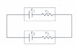
The equivalent emf is given by
\(\varepsilon_{\mathrm{eq}}=\frac{\varepsilon_{1} r_{2}+\varepsilon_{2} r_{1}}{r_{1}+r_{2}}\)...(I)
The equivalent internal resistance is given by
\(\frac{1}{r_{\mathrm{eq}}}=\frac{1}{r_{1}}+\frac{1}{r_{2}} \quad \text { or } \quad r_{\mathrm{eq}}=\frac{r_{1} r_{2}}{r_{1}+r_{2}}\)
Let us consider, two cells connected in parallel of same emf E and same internal resistance r.
From equatio. n (i), we get \(\varepsilon_{\mathrm{eq}}=\frac{\varepsilon r+\varepsilon r}{r+r}=\varepsilon\)
From equation (ii), we get
\(r_{\mathrm{eq}}=\frac{r^{2}}{r+r}=\frac{r}{2}\) -
(i) (a): Kirchhoff's Ist law is based on law of conservation of charge whereas Kirchhoff's IInd law is based on law of conservation of energy.
(ii) (c):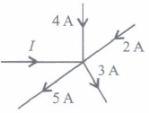
According to Kirchhoff's junction law
(+ I) + (+ 4 A) + (+ 2 A) + (- 5 A) + (- 3 A) = 0
I + 6 A - 8 A = 0 or I = 2 A
(iii) (c)
(iv) (d)
(v) (b):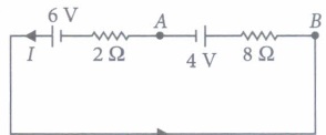
Apply KVL in the given circuit,
6 - 8I - 4 - 2I= 0
or, 2 - 10I= 0 or, I= 2/10 = 0.2 A
VAB = 4 + I x 8 = 4 + 0.2 x 8 = 5.6 V -
(I) (b): \((S+x)=\frac{Q}{P} R\)
\(x=\frac{Q}{P} R-S=\frac{6}{5} \times 10-5=7 \Omega\)
(ii) (a): A Wheatstone bridge consisting of four arms of resistance P, Q, R, S is most sensitive when all the resistances are equal.
(iii) (a) : When metal wire is heated, its resistance increases R1 increases,L1 increases.
The null point shift to the right.
(iv) (c): The percentage error in measuring resistance with a metre bridge can be minimized by adjusting the balancing point near the middle of the bridge i.e. close to 50 cm
(v) (c): \(\frac{P}{Q}=\frac{l_{1}}{100-l_{1}} \text { or } \frac{2}{3}=\frac{l_{1}}{100-l_{1}}\)
\(\text { or } \quad 5 l_{1}=200 \text { or } l_{1}=40 \mathrm{~cm}\) -
(i) (b)
(ii) (a): Given, \(I=1.0 \mathrm{~mA}=10^{-3} \mathrm{~A} ; R=4 \Omega ; L=4 \mathrm{~m}\)
Potential drop across potentiometer wire
V = IR = 10-3 X 4 V
Potential gradient, \(k=\frac{V}{L}=\frac{4 \times 10^{-3}}{4}\)
= 10-3 V m-1
(iii) (a)
(iv) (b): A potentiometer is an accurate and versatile device to make electrical measurements of EMF because the method involves a condition of no current flow through the galvanometer. It can be used to
measure potential difference, internal resistance of a cell and compare EMF's of two sources.
(v) (d):\(\frac{E_{1}}{E_{2}}=\frac{l_{1}+l_{2}}{l_{1}-l_{2}}=\frac{8+4}{8-4}=\frac{12}{4}=\frac{3}{1}\) -
(i) (c): According to Joule's law of heating, Heat produced in a conductor, H= I2Rt
where, I = Current flowing through the conductor
R = Resistance of the conductor
t = Time for which current flows through the conductor.
\(\therefore \quad H \propto I^{2}\)
(ii) (a): If the coil is cut into half, its resistance is also halved.
As \(H=\frac{V^{2}}{R} t \quad \therefore \quad H^{\prime}=2\)
(iii) (b): \(P=\frac{V^{2}}{R} \text { or } R=\frac{V^{2}}{P}\)
The bulbs are joined in series. Current in both the bulbs will same
\(\therefore\) The heat produced in them is given by H = I2Rt
or \(H \propto R \Rightarrow H \propto \frac{1}{P}\)
Therefore the bulb with low wattage or high resistance will glow brighter or we can say the 25 W bulb will glow brighter than the 100 W bulb.
(iv) (d): \(R=100 \Omega ; I=1 \mathrm{~A} ; t=5 \mathrm{~min} .=5 \times 60=300 \mathrm{~s}\)
change in internal energy = heat generated in coil
\(=I^{2} R t=\left((1)^{2} \times 100 \times 300\right) \mathrm{J}\)
= 30000 J = 30 kJ
(v) (d): Here, P = 100 W, t = 1 min = 60 s
Heat developed in time t
H = P x t = (100 W)( 60 s) = 6000 J -
(i) As soon as a circuit is closed, everywhere in conductor, electric field is set up (with the speed of light), and conduction electron at every point experiences a drift.
(ii) Each conduction electron does accelerate, and gain speed until it collides with a positive ion of a conductor, thereby loosing its drift speed after collision again it gains kinetic energy but suffers a collision again and so on. Therefore on the average, electron acquire only a drift speed
(iii) As number of the density of electrons \(\left(\approx 10^{29} \mathrm{~m}^{-3}\right)\) is very large, therefore current flowing is large.
(iv) No.
When electric field is applied, the net drift of the electrons is from lower to higher potential. But locally electrons collide with ions and may change its direction during the course of their motion.
(v) Yes. In the (a) absence of electric field, the paths are straight lines.
Reason: As electrons were not acted upon by any kind of forces.
(b) No. In the presence of electric field paths were curved. Reason: As direction of random velocities and acceleration are not always same. -
(i) \(\text { (i) Potential gradient }=\frac{\mathrm{emf}}{\text { balancing length }}\)
\(=\frac{2 \mathrm{~V}}{5 \mathrm{~m}}\) [\(\because\)1 = 500 cm = 5 m]
\(k=\frac{2}{5} \mathrm{Vm}^{-1}\)
(ii) Voltmeter Reading = V = k l'; l' = 490 cm
= 4.9 m
\(\therefore \quad V=\frac{2}{5} \times 4.9=1.96 \mathrm{~V}\)
(iii) When voltmeter is connected across the cell

If current through voltmeter is I, then P.D. across the cell is given by
V = E -lr
1.96 = 2.0 - I x 10
I = 0.004 A

\(\text { Slope }=\frac{\Delta V}{\Delta l}=k=\text { Potential gradient }\) -
(i) VAB = E1 = 2V [r1 = 0]
lAB = 1 m
\(\therefore\) Potential gradient
\(k=\frac{\mathrm{V}_{\mathrm{AB}}}{l_{\mathrm{AB}}}=\frac{2}{1} \frac{\mathrm{V}}{\mathrm{m}}\)
\(\therefore\) k = 2 Vm-1
(ii) IAc = 60cm = 0.6m [given]
and E2 is balanced against lAC
\(\therefore \ k=\frac{\mathrm{E}_{2}}{0.6}=2\)
\(\Rightarrow \ E_{2}=1.2 \mathrm{~V}\)
(iii) No. As no current flows through E2 at the balancing condition. -
(i) Let J be the null point. Then
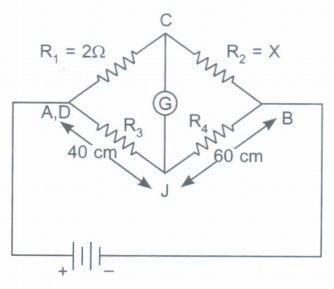
(ii) Here AJ = 40 cm = 0040 m
JB = 60 cm = 0.60 m
If resistance gradient is r \(\Omega\) m-1
then resistance of wire of length AJ is R3 = r x 0.4 \(\Omega\)
then resistance of wire of length ill is R4 = r x 0.6 \(\Omega\)
\(\therefore\) According to Wheatstone Bridge Principle, at balancing point
\(\frac{R_{1}}{R_{2}}=\frac{R_{3}}{R_{4}}\)
\(\frac{2}{X}=\frac{0.4 r}{0.6 r}\)
or X = 3 \(\Omega\)
(iii) If 6\(\Omega\) is connected in parallel to X = 3\(\Omega\) then, equivalent resistance in parallel is given by
\(X_{P}=\frac{3 \times 6}{3+6}=2 \Omega\)
Now R1 = 2\(\Omega\), R2 = Xp = 2 \(\Omega\)
R3 = rl, R4 = r(100-1)
here l = balancing length
\(\therefore \ \frac{R_{1}}{R_{2}}=\frac{R_{3}}{R_{4}}\)
\(\Rightarrow \ \frac{2}{2}=\frac{r l}{r(100-l)}\)
\(\therefore\)100- l = l
l = 50 cm. -
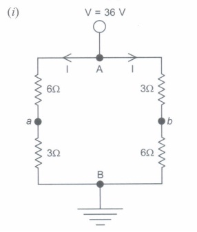
Voltage at A VA = 36 V
If I is current through each branch, then
\(\mathrm{I}=\frac{36}{6+3}=4 \mathrm{~A}\)
\(\therefore\) VA - Va = 6I
36 - Va = 6 x 4
va = 36 - 24 = 12V
and VA -Vb = 3I
36 - Vb = 3 x 4
36 - Vb = 3 x 4
Vb = 36 - 12 = 24V
Va-Vb = 12 - 24 = -12V
(ii) When switch S is closed
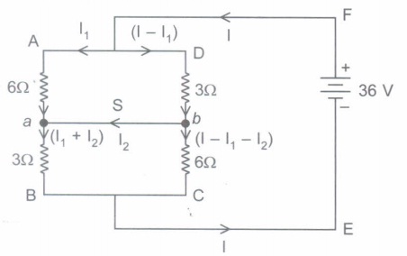
Using Kirchoff's loop rule in loop AabDA
6I1 + 3(I - I1) = 0
\(\Rightarrow\) 3I = 9I1
\(\Rightarrow\)I = 3I1 ...(i)
Applying KVL for loop aBCba
-3(I1 + I2 )+ 6(I - I1 - I2 )= 0
-3I1 - 3I2 + 6I - 6I1 - 6I2 = 0
-9I1 - 9I2 + 6 x 3I1 = 0 (using eq. (i))
9I1 = 9I2
\(\Rightarrow\) I1 = I2 ...(ii)
using loop AaBEFA
- 6I1 - 3(I1 + I2 )+ 36 = 0
- 6I2 - 3(I2 + I2 ) = -36
\(\Rightarrow\) I2 = 3A
3A current will flow through the switch from b to a. -
(i)

\(\because\) 6\(\Omega\) and 3\(\Omega\) are connected in series
Req = 6 + 3
= 9\(\Omega\)
\(\therefore \ \mathrm{I}=\frac{\mathrm{P} \cdot \mathrm{D} .}{\mathrm{R}_{e q}}\)
\(=\frac{18-0}{9}\)
= 2A
\(\therefore\) VA - Va = 6I
18 - 6 x 2 = V a
\(\therefore\) Va = 6V ..........(i)

6\(\mu\)F and 3\(\mu\)F capacitors are in series.
\(\therefore \ C_{e q}=\frac{6 \times 3}{6+3}\)
= 2\(\mu\) F
\(\therefore\) Charge on 6\(\mu\)F = Charge on 3\(\mu\)F = Charge withdrawn
\(\therefore\) Q = Ceq x P.D.
= 2 x 10-6 x 18
= 36 x 10-6 C = 36 \(\mu\)F
\(\therefore\) Potential difference across 6\(\mu\)F is given by
\(18-\mathrm{V}_{b}=\frac{\mathrm{Q}}{6 \times 10^{-6}}\)
\(18-\frac{36 \times 10^{-6}}{6 \times 10^{-6}}=\mathrm{V}_{b}\)
\(\Rightarrow\)Vb = 12V
\(\therefore\) Vab = 12 - 6 = 6V
(ii) When switch S is closed then
\(\text { (P.D.) }_{6 \Omega}=\text { (P.D.) }_{6 \mu \mathrm{F}} \text { and }(\mathrm{P} . \mathrm{D} .)_{3 \Omega}=(\mathrm{P.D} .)_{3 \mu \mathrm{F}}\) as 6\(\Omega\) resistor and 6\(\mu\)F capacitor are in parallel and, 3\(\Omega\) resistor and 3\(\mu\)F capacitor are in parallel.
\(\therefore\) Va = Vb = 6V (using eq. (i) in part (a))
(iii) When switch is closed, P.D. across capacitor of capacitance 6\(\mu\)F is = 18 - 6 = 12V
\(\therefore\) Electric charge stored after closing S in it is
Q = CV = 6 x 10-6 x 12 = 72\(\mu\)C
\(\therefore\) Charge that will flow through capacitor and is equal to = 72 - 36 = 36\(\mu\)C.
Case Study