

Class 12th Physics - Moving Charges And Magnetism Case Study Questions and Answers 2022 - 2023
QB365 provides a detailed and simple solution for every Possible Case Study Questions in Class 12th Physics Subject - Moving Charges And Magnetism, CBSE. It will help Students to get more practice questions, Students can Practice these question papers in addition to score best marks.
QB365 - Question Bank Software
Moving Charges And Magnetism Case Study Questions With Answer Key
12th Standard CBSE
-
Reg.No. :
Physics
-
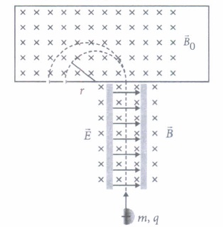
Various methods can be used to measure the mass of an atom. One possibility is through the use of a mass spectrometer. The basic feature of a Banbridge mass spectrometer is illustrated in figure. A particle carrying a charge +q is first sent through a velocity selector and comes out with velocity v = E/B.
The applied electric and magnetic fields satisfy the relation E = vB so that the trajectory of the particle is a straight line. Upon entering a region where a second magnetic field \(\vec{B}_{0}\) pointing into the page has been applied, the particle will move in a circular path with radius r and eventually strike the photographic plate.
(i) In mass spectrometer, the ions are sorted out in which of the following ways?(a) By accelerating them through electric field (b) By accelerating them through magnetic field (c) By accelerating them through electric and magnetic field (d) By applying a high voltage (ii) Radius of particle in second magnetic field Bo is
\(\text { (a) } \frac{2 m v}{q E_{0}}\) \(\text { (b) } \frac{m v}{q E_{0}}\) \(\text { (c) } \frac{m v}{q B_{0}}\) \(\text { (d) } \frac{2 m E_{0} v}{q B_{0}}\) (iii) Which of the following will trace a circular trajectory wit largest radius?
(a) Proton (b) -\(\alpha\)particle (c) Electron (d) A particle with charge twice and mass thrice that of electron (iv) Mass of the particle in terms q, Bo, B,r and E is
\(\text { (b) } \frac{q B_{0} B r}{E}\) \(\text { (c) } \frac{q B r}{E B_{0}}\) \(\text { (d) } \frac{q B r E}{B_{0}}\) (v) The particle comes out of velocity selector along a straight line, because
(a) electric force is less than magnetic force (b) electric force is greater than magnetic force (c) electric and magnetic force balance each other (d) can't say. -
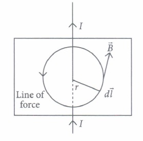
Ampere's law gives a method to calculate the magnetic field due to given current distribution. According to it, the circulation \(\oint \vec{B} \cdot d \vec{l}\) of the resultant magnetic field along a closed plane curve is equal to \(\mu_{0}\) times the total current crossing the area bounded by the closed curve provided the electric field inside the loop remains constant. Ampere's law is more useful under certain symmetrical conditions. Consider one such case of a long Straight wire with circular cross-section (radius R) carrying current I uniformly distributed across this cross-section.
(i) The magnetic field at a radial distance r from the centre of the wire in the region r > R, is\(\text { (a) } \frac{\mu_{0} I}{2 \pi r}\) \(\text { (b) } \frac{\mu_{0} I}{2 \pi R}\) \(\text { (c) } \frac{\mu_{0} I R^{2}}{2 \pi r}\) \(\text { (d) } \frac{\mu_{0} I r^{2}}{2 \pi R}\) (ii) The magnetic field at a distance r in the region r < R is
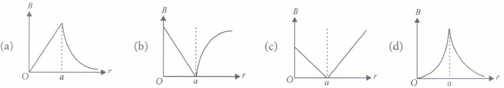
\(\text { (a) } \frac{\mu_{0} I}{2 r}\) \(\text { (b) } \frac{\mu_{0} I r^{2}}{2 \pi R^{2}}\) \(\text { (c) } \frac{\mu_{0} I}{2 \pi r}\) \(\text { (d) } \frac{\mu_{0} I r}{2 \pi R^{2}}\) (iii) A long straight wire of a circular cross section (radius a) carries a steady current I and the current I is uniformly distributed across this cross-section. Which of the following plots represents the variation of magnitude of magnetic field B with distance r from the centre of the wire?
(iv) A long straight wire of radius R carries a steady current I. The current is uniformly distributed across its cross-section. The ratio of magnetic field at R/2 and 2R is\(\text { (a) } \frac{1}{2}\) (b) 2 \(\text { (c) } \frac{1}{4}\) (d) 1 (v) A direct current I flows along the length of an infinitely long straight thin walled pipe, then the magnetic field is
(a) uniform throughout the pipe but not zero (b) zero only along the axis of the pipe (c) zero at any point inside the pipe (d) maximum at the centre and minimum at the edges. -
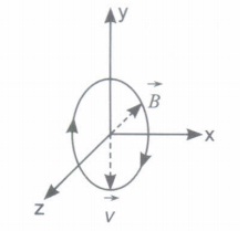
The path of a charged particle in magnetic field depends upon angle between velocity and magnetic field.If velocity \(\vec{v}\) is at angle \(\theta\) to \(\vec{B}\) component of velocity parallel to magnetic field \((v \cos \theta)\) remains constant and component of velocity perpendicular to magnetic field \((v \sin \theta)\) is responsible for circular motion, thus the charge particle moves in a helical path.
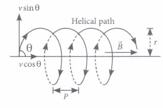
The plane of the circle is perpendicular to the magnetic field and the axis of the helix is parallel to the magnetic field. The charged particle. moves along helical path touching the line parallel to the magnetic field passing through the starting point after each rotation.
Radius of circular path is \(r=\frac{m v \sin \theta}{1 v_{q} B}\)
Hence the resultant path of the charged particle will be a helix, with its axis along the direction of \(\vec{B}\) as shown in figure.
(i) When a positively charged particle enters into a uniform magnetic field with uniform velocity, its trajectory can be (i) a straight line (ii) a circle (iii) a helix.(a) (i) only (b) (i) or (ii) (c) (i) or (iii) (d) anyone of (i), (ii) and (iii) (ii) Two charged particles A and B having the same charge, mass and speed enter into a magnetic field in such a way that the initial path of A makes an angle of 30° and that of B makes an angle of 90° with the field. Then the trajectory of
(a) B will have smaller radius of curvature than that of A (b) both will have the same curvature (c) A will have smaller radius of curvature than that of B (d) both will move along the direction of their original velocities. (iii) An electron having momentum 2.4 x 10⁻²³kg m/ s enters a region of uniform magnetic field of 0.15 T. The field vector makes an angle of 30° with the initial velocity vector of the electron. The radius of the helical path of the electron in the field shall be
(a) 2 mm (b) 1 mm \(\text { (c) } \frac{\sqrt{3}}{2} \mathrm{~mm}\) (d) 0.5 mm (iv) The magnetic field in a certain region of space is given by \(\vec{B}=8.35 \times 10^{-2} \hat{i}\) T. A proton is shot into the field with velocity \(\vec{v}=\left(2 \times 10^{5} \hat{i}+4 \times 10^{5} \hat{j}\right) \mathrm{m} / \mathrm{s}\) The proton follows a helical path in the field. The distance moved by proton in the x-direction during the period of one revolution in the yz-plane will be
(Mass of proton = 1.67 x 10⁻²⁷kg)(a) 0.053 m (b) 0.136 m (c) 0.157 m (d) 0.236 m (v) The frequency of revolution of the particle is
\(\text { (a) } \frac{m}{q B}\) \(\text { (b) } \cdot \frac{q B}{2 \pi m}\) \(\text { (c) } \frac{2 \pi R}{v \cos \theta}\) \(\text { (d) } \frac{2 \pi R}{v \sin \theta}\) -
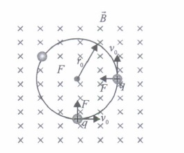
An electron with speed Vo << c moves in a circle ofradius ro in a uniform magnetic field. This electron is able to traverse a circular path as magnetic field is perpendicular to the velocity of the electron. A force acts on the particle perpendicular to both \(\vec{v}_{0}\) and \(\vec{B}\). This force continuously deflects the particle sideways without changing its speed and the particle will move along a circle perpendicular to the field. The time required for one revolution of the electron is To .
(i) If the speed of the electron is now doubled to 2vo.The radius of the circle will change to\(\text { (a) } 4 r_{0}\) \(\text { (b) } 2 r_{0}\) \(\text { (c) } r_{0}\) \(\text { (d) } r_{0} / 2\) (ii) If vo = 2vo then the time required for one revolution of the electron will change to
\(\text { (a) } 4 T_{0}\) \(\text { (b) } 2 T_{0}\) \(\text { (c) } T_{0}\) \(\text { (d) } T_{0} / 2\) (iii) A charged particles is projected in a magnetic field \(\vec{B}=(2 \hat{i}+4 \hat{j}) \times 10^{2} \mathrm{~T}\) The acceleration of the particle is found to be \(\vec{a}=(x \hat{i}+2 \hat{j}) \mathrm{m} \mathrm{s}^{-2}\). Find the value of x.
(a) 4 m S-2 (b) -4 m s-2 (c) -2 m s-2 (d) 2 m s-2 (iv) If the given electron has a velocity not perpendicular to B, then trajectory of the electron is
(a) straight line (b) circular (c) helical (d) zig-zag (v) If this electron of charge (e) is moving parallel to uniform magnetic field with constant velocity v, the force acting on the electron is
(a) Bev \(\text { (b) } \frac{B e}{v}\) \(\text { (c) } \frac{B}{e v}\) (d) zero -
When a rectangular loop PQRS of sides 'a' and 'b' carrying current I is placed in uniform magnetic field \(\vec{B}\) such that area vector \(\vec{A}\) makes an angle \(\theta\) with direction of magnetic field, then forces on the arms QR and SP of loop are equal, opposite and collinear, thereby perfectly cancel each other, whereas forces on the arms PQ and RS of loop are equal and opposite but not collinear, so they give rise to torque on the loop.
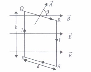
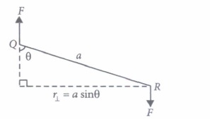
Force on side PQ or RS ofloop is F = IbB sin 90° = Ib B and perpendicular distance between two non-collinear forces is \(r_{\perp}\) = a sin \(\theta\)
So, torque on the loop, \(\tau=I A B \sin \theta\)
In vector form torque \(\vec{\tau}=\vec{M} \times \vec{B}\)
where \(\vec{M}=N I \vec{A}\) is called magnetic dipole moment of current loop and is directed in direction of area vector \(\vec{A}\) i.e., normal to the plane ofloop.
(i) A circular loop of area 1 cm2, carrying a current of 10 A is placed in a magnetic field of 0.1T perpendicular to the plane of the loop. The torque on the loop due to the magnetic field is(a) zero (b) 10-4 N m (c) 10-2 N m (d) 1N m (ii) Relation between magnetic moment and angular velocity is
\(\text { (a) } M \propto \omega\) \(\text { (b) } M \propto \omega^{2}\) \(\text { (c) } M \propto \sqrt{\omega}\) (d) none of these (ill) A current loop in a magnetic field
(a) can be in equilibrium in two orientations, both the equilibrium states are unstable (b) can be in equilibrium in two orientations, one stable while the other is unstable (c) experiences a torque whether the field is uniform or non uniform in all orientations (d) can be in equilibrium in one orientation (iv) The magnetic moment of a current I carrying circular coil of radius r and number of turns N varies as
\(\text { (a) } \frac{1}{r^{2}}\) \(\text { (b) } \frac{1}{r}\) (c) r (d) r2 (v) A rectangular coil carrying current is placed in a non-uniform magnetic field. On that coil the total
(a) force is non-zero (b) force is zero (c) torque is zero (d) none of these (i) (c): In mass spectrometer, the ions are sorted out by accelerating them through electric and magnetic field.
-
A magnetic field can be produced by moving, charges or electric currents. The basic equation governing the magnetic field due to a current distribution is the Biot-Savart law.
Finding the magnetic field resulting from a current distribution involves the vector product, and is inherently a calculas problem when the distance from the current to the field point is continuously changing.
According to this law, the magnetic field at a point due to a current element oflength \(d \vec{l}\) carrying current I, at a distance r from the element is \(d B=\frac{\mu_{0}}{4 \pi} \frac{I(d \vec{l} \times \vec{r})}{r^{3}}\)
Biot -Savart law has certain similarities as well as difference with Coloumbs law for electrostatic field e.g., there is an angle dependence in Biot-Savart law which is not present in electrostatic case.
(i) The direction of magnetic field \(d \vec{B}\) due to a current element \(I d \vec{l}\) at a point of distance \(\vec{r}\) from it, when a current I passes through a long conductor is in the direction\(\text { (a) of position vector } \vec{r} \text { of the point }\) \(\text { (b) of current element } d \vec{l}\) \(\text { (c) perpendicular to both } d \vec{l} \text { and } \vec{r}\) \(\text { (d) perpendicular to } d \vec{l} \text { only }\) (ii) The magnetic field due to a current in a straight wire segment of length L at a point on its perpendicular bisector at a distance r (r >> L)
\(\text { (a) decreases as } \frac{1}{r} \text { . }\) \(\text { (b) decreases as } \frac{1}{r^{2}} \text { . }\) \(\text { (c) decreases as } \frac{1}{r^{3}} \text { . }\) \(\text { (d) approaches a finite limit as } r \rightarrow \infty\) (iii) Two long straight wires are set parallel to each other. Each carries a current i in the same direction and the separation between them is 2r. The intensity of the magnetic field midway t between them is
\(\text { (a) } \mu_{0} i / r\) \(\text { (b) } 4 \mu_{0} i / r\) (c) zero \(\text { (d) } \mu_{0} i / 4 r\) (iv) A long straight wire carries a current along the z-axis for any two points in the x - y plane. Which of the following is always false?
(a) The magnetic fields are equal (b) The directions of the magnetic fields are the same (c) The magnitudes ofthe magnetic fields are equal (d) The field at one point is opposite to that at the other point (v) Biot-Savart law can be expressed alternatively as
(a) Coulomb's Law (b) Ampere's circuital law (c) Ohm's Law (d) Gauss's Law -
Moving coil galvanometer operates on Permanent Magnet Moving Coil (PMMC) mechanism and was designed by the scientist D'arsonval.
Moving coil galvanometers are of two types
(i) Suspended coil
(ii) Pivoted coil type or tangent galvanometer.
Its working is based on the fact that when a current carrying coil is placed in a magnetic field, it experiences a torque. This torque tends to rotate the coil about its axis of suspension in such a way that the magnetic flux passing through the coil is maximum.
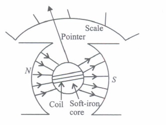
(i) A moving coil galvanometer is an instrument which(a) is used to measure emf (b) is used to measure potential difference (c) is used to measure resistance (d) is a deflection instrument which gives a deflection when a current flows through its coil (ii) To make the field radial in a moving coil galvanometer
(a) number of turns of coil is kept small (b) magnet is taken in the form of horse-shoe (c) poles are of very strong magnets (d) poles are cylindrically cut (iii) The deflection in a moving coil galvanometer is
(a) directly proportional to torsional constant of spring (b) directly proportional to the number of turns in the coil (c) inversely proportional to the area of the coil (d) inversely proportional to the current in the coil (iv) In a moving coil galvanometer, having a coil of N-turns of area A and carrying current I is placed in a radial field of strength B.
The torque acting on the coil is\(\text { (a) } N A^{2} B^{2} I\) \(\text { (b) } N A B I^{2}\) \(\text { (c) } N^{2} A B I\) (d) NABI (v) To increase the current sensitivity of a moving coil galvanometer, we should decrease
(a) strength of magnet (b) torsional constant of spring (c) number ofturns in coil (d) area of coil -
A galvanometer can be converted into voltmeter of given range by connecting a suitable resistance Rs in series with the galvanometer, whose value is given by
\(R_{s}=\frac{V}{I_{g}}-G\)
where V is the voltage to be measured, Ig is the current for full scale deflection of galvanometer and G is the resistance of galvanometer
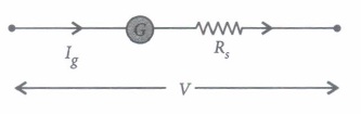
Series resistort (Rs) increases range of voltmeter and the effective resistance of galvanometer. It also protects the galvanometer from damage due to large current.
Voltmeter is a high resistance instrument and it is always connected in parallel with the circuit element across which potential difference is to be measured. An ideal voltmeter has infinite resistance
In order to increase the range of voltmeter n times the value of resistance to be connected in series with galvanometer is Rs = (n - l)G.
(I) 10 mA current can pass through a galvanometer of resistance \(25 \Omega\) What resistance in series should be connected through it, so that it is converted into a voltmeter of 100 V?\(\text { (a) } 0.975 \Omega\) \(\text { (b) } 99.75 \Omega\) \(\text { (c) } 975 \Omega\) \(\text { (d) } 9975 \Omega \text { . }\) (ii) There are 3 voltmeter A, B, C having the same range but their resistance are \(15,000 \Omega, 10,000 \Omega\) and \(5,000 \Omega\) respectively. The best voltmeter amongst them is the one whose resistance is
\(\text { (a) } 5000 \Omega\) \(\text { (b) } 10,000 \Omega\) \(\text { (c) } 15,000 \Omega\) (d) all are equally good (iii) A milliammeter of range 0 to 25 mA and resistance of \(10 \Omega\) is to be converted into a voltmeter with a range of 0 to 25 V. The resistance that should be connected in series will be
(a) \(930 \Omega\) \(\text { (b) } 960 \Omega\) \(\text { (c) } 990 \Omega\) \(\text { (d) } 1010 \Omega\) (iv) To convert a moving coil galvanometer (MCG) into a voltmeter
(a) a high resistance R is connected in parallel with MCG (b) a low resistance R is connected in parallel with MCG (c) a low resistance R is connected in series with MCG (d) a high resistance R is connected in series with MCG (v) The resistance of an ideal voltmeter is
(a) zero (b) low (c) high (d) infinity -
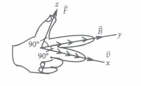
A charged particle moving in a magnetic field experiences a force that is proportional to the strength of the magnetic field, the component of the velocity that is perpendicular to the magnetic field and the charge of the particle.
This force is given by \(\vec{F}=q(\vec{v} \times \vec{B})\) where q is the electric charge of the particle, v is the instantaneous velocity of the particle, and B is the magnetic field (in tesla).
The direction of force is determined by the rules of cross product of two vectors
Force is perpendicular to both velocity and magnetic field. Its direction is same as \(\vec{v} \times \vec{B}\) if q is positive and opposite of \(\vec{v} \times \vec{B}\) if q is negative
The force is always perpendicular to both the velocity of the particle and the magnetic field that created it. Because the magnetic force is always perpendicular to the motion, the magnetic field can do no work on an isolated charge. It can only do work indirectly, via the electric field generated by a changing magnetic field.
(I) When a magnetic field is applied on a stationary electron, it(a) remains stationary (b) spins about its own axis (c) moves in the direction of the field (d) moves perpendicular to the direction of the field. (ii) A proton is projected with a uniform velocity v along the axis of a current carrying solenoid, then
(a) the proton will be accelerated along the axis (b) the proton path will be circular about the axis (c) the proton moves along helical path (d) the proton will continue to move with velocity v along the axis. (iii) A charged particle experiences magnetic force in the presence of magnetic field. Which of the following statement is correct?
(a) The particle is stationary and magnetic field is perpendicular. (b) The particle is moving and magnetic field is perpendicular to the velocity (c) The particle is stationary and magnetic field is parallel (d) The particle is moving and magnetic field is parallel to velocity (iv) A charge q moves with a velocity 2 ms-1 along x-axis in a uniform magnetic field \(\vec{B}=(\hat{i}+2 \hat{j}+3 \hat{k}) \mathrm{T}\) then charge will experience a force
(a) in z-y plane (b) along -yaxis (c) along +z axis (d) along -z axis (v) Moving charge will produce
(a) electric field only (b) magnetic field only (c) both electric and magnetic field (d) none ofthese. -
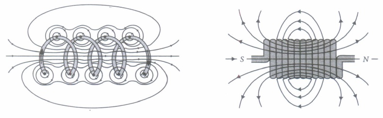
A solenoid is a long coil of wire tightly wound in the helical form. Solenoid consists of closely stacked rings electrically insulated from each other wrapped around a non-conducting cylinder.
Figure below shows the magnetic field lines of a solenoid carrying a steady current 1.We see that if the turns are closely spaced, the resulting magnetic field inside the solenoid becomes fairly uniform, provided that the length of the solenoid is much greater than its diameter, For an "ideal" solenoid, which is infinitely long with turns tightly packed, the magnetic field inside the solenoid is uniform and parallel to the axis, and vanishes outside the solenoid.
(i) Along solenoid has 800 turns per metre length of solenoid. A current of 1.6A flows through it. The magnetic induction at the end of the solenoid on its axis is(a) 16 x 10-4 T (b) 8 x 10⁻⁴ T (c) 32 X 10-4 T (d) 4 x 10⁻⁴ T (ii) Choose the correct statement in the following
(a) The magnetic field inside the solenoid is less than that of outside (b) The magnetic field inside an ideal solenoid is not at all uniform (c) The magnetic field at the centre, inside an ideal solenoid is atmost twice that at the ends (d) The magnetic field at the centre, inside an ideal solenoid is almost half of that at the ends (iii) The magnetic field (B) inside a long solenoid having n turns per unit length and carrying current I when iron core is kept in it is \(\left(\mu_{0}=\text { permeability of vacuum, } \chi=\right.\text { magnetic susceptibility) }\)
\(\text { (a) } \mu_{0} n I(1-\chi)\) \(\text { (b) } \mu_{0} n I \chi\) \(\text { (c) } \mu_{0} n I^{2}(1+\chi)\) \(\text { (d) } \mu_{0} n I(1+\chi)\) (iv) A solenoid oflength I and having n turns carries a current I is in anticlockwise direction. The magnetic field is
\(\text { (a) } \mu_{0} n I\) \(\text { (b) } \mu_{0} \frac{n I}{l^{2}}\) (c) along the axis of solenoid (d) perpendicular to the axis of coil (v) The magnitude of the magnetic field inside a long solenoid is increased by
(a) decreasing its radius (b) decreasing the current through it (c) increasing its area of cross-section (d) introducing a medium of higher permeability -
Electric fields interact with both stationary and moving charges while magnetic fields affect only moving charges. Therefore, when a charged particle of charge q and mass m moving with velocity 'v' enters a region where both eletric \((\vec{E})\) and magnetic \((\vec{B})\) fields are simultaneously applied, then this charge particle will experience a force called Lorentz force given by
\(\vec{F}=q \vec{E}+q(\vec{v} \times \vec{B})\)
and the motion of the charged particle is quite complicated. But by adjusting the value of \((\vec{E})\) and \((\vec{B})\) the velocity of.charge particle can be controlled.
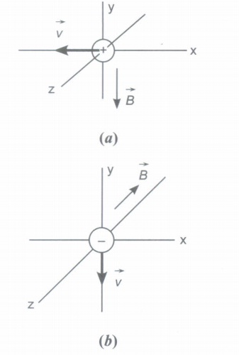
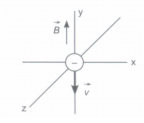
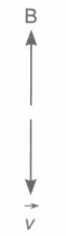
(i) The figure below shows three situation in which a charged particle with velocity \(\vec{v}\) travels through a uniform magnetic field \(\overrightarrow{\boldsymbol{B}}\). In each situation, what is the direction of the magnetic force \(\overrightarrow{F_{B}}\) on the particle? Also, draw the trajectory of particle in each case.
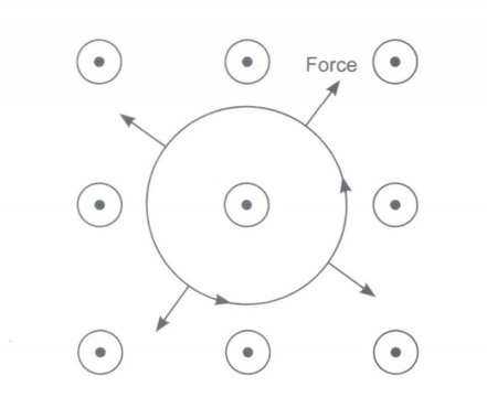
(ii) In the adjoining figure four directions for the velocity vector \(\vec{v}\)of a positively charged particle moving through a uniform electric field \(\overrightarrow{\boldsymbol{E}}\) (directed into the page and represent by \(\otimes \text { ) }\)and a unform magnetic field \(\overrightarrow{\boldsymbol{B}}\) .
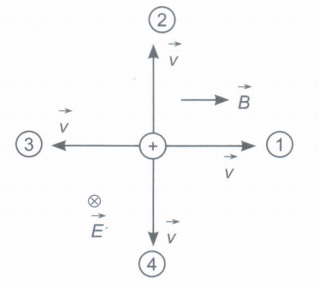
(a) Rank directions 1, 2 and 3 according to the magnitude of the net force on the particle, greatest first.
(b) Among all four directions, which might result in a net force of zero? -
Figure shows a rectangular coil ABCD placed between magnetic N-pole and S-pole.
There is a current in the coil
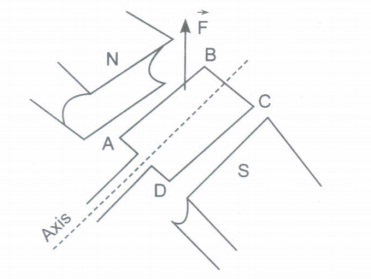
An upward force F = 9.6 x 10⁻³ N is acting on the side AB of the coil.
(i) (a) Explain why there is a force on side AB.
(b) Determine the direction of current in AB and state how the direction is deduced.
(ii) Both sides AB and CD of the coil are at a distance 2 cm from the axis. Determine the moment acting on the coil ABCD.
(iii) For which purpose above arrangement can be used?
In which device above arrangement is used? -
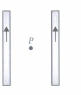
A loop of flexible conducting wire of length 31.4 cm carrying current of 1.5 A is placed in a magnetic field as shown. If current flowing through the wire in anticlockwise direction is switched on then what will be
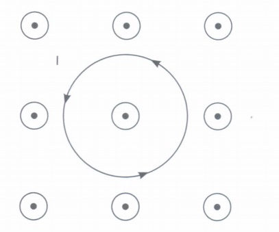
(i) the shape of the loop?
(ii) determine net magnetic field at the centre of the loop. If it is given that current carrying loop is placed in a region having external magnetic field of 3.6 G. -
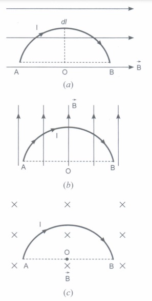
What is the force experienced by a semi-circular wire of radius R carrying current 'I' and is placed in a region where uniform magnetic flux density (B) is as shown in the figures (a), (b) and (c) respectively?
-
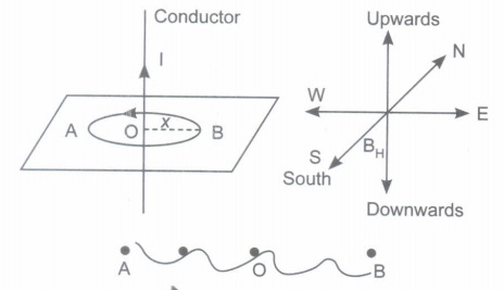
If a straight current carrying conductor is placed as shown. Points A and B lies on west and east side of a conductor at a distance x each from the conductor. Then relate the magnetic field at A to that at B. Also draw the corresponding magnetic field lines.
Case Study
*****************************************
Answers
Moving Charges And Magnetism Case Study Questions With Answer Key Answer Keys
-
(i) (c): In mass spectrometer, the ions are sorted out by accelerating them through electric and magnetic field.
(ii) (c): As \(\frac{m v^{2}}{r}=q v B_{0} \therefore r=\frac{m v}{q B_{0}}\)
(iii) (b): As radius \(r \propto \frac{m}{q}\)
\(\therefore\) r will be maximum for \(\alpha\) - particle.
(iv) (b) : Here, \(r=\frac{m v}{q B_{0}} \text { or } m=\frac{r q B_{0}}{v}\)
As \(v=\frac{E}{B}, \therefore m=\frac{q B_{0} B r}{E}\)
(v) (c): From the relation v = E/B, it is clear electric and magnetic force balance each other. -
(i) (a) :Magnetic field due to a long current carrying wire at r
\(B=\frac{\mu_{0}}{2 \pi} \frac{I}{r}\)
(ii) (d): Let I' be the current in region r < R
Then, \(I^{\prime}=\frac{I}{\pi R^{2}} \pi\left(r^{2}\right) \text { or } I^{\prime}=\frac{I r^{2}}{R^{2}}\)
So, magnetic. field \(B=\frac{\mu_{0} I^{\prime}}{2 \pi r}=\frac{\mu_{0} I r^{2}}{2 \pi R^{2} r}=\frac{\mu_{0} I r}{2 \pi R^{2}}\)
(iii) (a): Magnetic field due to a long straight wire of radius a carrying current I at a point distant r from the centre of the wire is given as follows

\(B=\frac{\mu_{0} I r}{2 \pi a^{2}} \quad \text { for } \quad r<a\)
\(B=\frac{\mu_{0} I}{2 \pi a} \quad \text { for } r=a\)
\(B=\frac{\mu_{0} I}{2 \pi r} \quad \text { for } r>a\)
The variation of magnetic field B with distance r from the centre of wire is shown in the figure.
(iv) (d): Let the magnetic fields due to a long straight wire of radius R carrying a steady current I at a distance r from the centre of the wire are
\(B_{1}=\frac{\mu_{0} I r}{2 \pi R^{2}} \quad(\text { For } r<R)\)
and \(B_{2}=\frac{\mu_{0} I}{2 \pi R} \quad(\text { For } r>R)\)
So, the magnetic field at \(r=\frac{R}{2} \text { is } B_{1}=\frac{\mu_{0} I}{2 \pi R^{2}}\left(\frac{R}{2}\right)=\frac{\mu_{0} I}{4 \pi R}\)
and at \(r=2 R \text { is } B_{2}=\frac{\mu_{0} I}{2 \pi(2 R)}=\frac{\mu_{0} I}{4 \pi R}\)
\(\therefore\) Their corresponding ratio is \(\frac{B_{1}}{B_{2}}=\frac{\left(\mu_{0} I / 4 \pi R\right)}{\left(\mu_{0} I / 4 \pi R\right)}=1\)
(v) (c) -
(i) (d)
(ii) (a): Using \(q v B \sin \theta=\frac{m v^{2}}{r}\)
\(r \propto \frac{1}{\sin \theta}\) for the same values of m, v, q and B
\(\therefore \frac{r_{A}}{r_{B}}=\frac{\sin 90^{\circ}}{\sin 30^{\circ}}=2 \text { or } r_{A}=2 r_{B} \text { or } r_{B}<r_{A}\)
(iii) (d): The radius of the helical path of the electron in the uniform magnetic field is
\(r=\frac{m v_{\perp}}{e B}=\frac{m v \sin \theta}{e B}=\frac{\left(2.4 \times 10^{-23} \mathrm{~kg} \mathrm{~m} / \mathrm{s}\right) \times \sin 30^{\circ}}{\left(1.6 \times 10^{-19} \mathrm{C}\right) \times 0.15 \mathrm{~T}}\)
\(=5 \times 10^{-4} \mathrm{~m}=0.5 \times 10^{-3} \mathrm{~m}=0.5 \mathrm{~mm}\)
(iv) (c): Here \(\vec{B}=8.35 \times 10^{-2} \hat{i} \mathrm{~T}\)
\(\vec{v}=2 \times 10^{5} \hat{i}+4 \times 10^{5} \hat{j} \mathrm{~m} / \mathrm{s}, m=1.67 \times 10^{-27} \mathrm{~kg}\)
Pitch of the helix (i.e., the linear distance moved along the magnetic field in one rotation) is given by
Pitch of the helix \(=\frac{2 \pi m v_{\|}}{q B}\)
\(=\frac{2 \times 3.14 \times 1.67 \times 10^{-27} \times 2 \times 10^{5}}{1.6 \times 10^{-19} \times 8.35 \times 10^{-2}}=0.157 \mathrm{~m}\)
(v) (b): Period of revolution
\(T=\frac{2 \pi R}{v \sin \theta} \Rightarrow T=\frac{2 \pi\left(\frac{m v \sin \theta}{q B}\right)}{v \sin \theta} \Rightarrow T=\frac{2 \pi m}{q B}\)
\(\therefore \text { Frequency, } v=\frac{1}{T}=\frac{q B}{2 \pi m}\) -
(i) (b): As \(r_{0}=\frac{m v}{q B} \Rightarrow r^{\prime}=\frac{m\left(2 v_{0}\right)}{q B}=2 r_{0}\)
(ii) (c): As, \(T=\frac{2 \pi m}{q B}\)
Thus, it remains same as it is in dependent of velocity
(iii) (b): As \(F \perp B\)
Hence, \(a \perp B\)
\(\therefore \vec{a} \cdot \vec{B}=0\)
\(\Rightarrow \quad(x \hat{i}+2 \hat{j}) \cdot(2 \hat{i}+4 \hat{j})=0\)
\(2 x+8=0 \Rightarrow x=-4 \mathrm{~m} \mathrm{~s}^{-2}\)
(iv) (c): If the charged particle has a velocity not perpendicular to \(\vec{B},\) then component of velocity along \(\vec{B}\) remains unchanged as the motion along the \(\vec{B}\) will not be affected by \(\vec{B}\).
Then, the motion of the particle in a plane perpendicular to \(\vec{B}\) is as before circular one. Thereby, producing helical motion.
(v) (d): The force on electron \(F=q v B \sin \theta\)
As the electron is moving parallel to B
So,\(\theta=0^{\circ} \Rightarrow q v B \sin 0^{\circ}=0\) -
(I) (a): Torque on a current carrying loop in magnetic field \(\tau=I B A \sin \theta\)
Here, \(I=10 \mathrm{~A}, B=0.1 \mathrm{~T}, A=1 \mathrm{~cm}^{2}=10^{-4} \mathrm{~m}^{2}, \theta=0^{\circ}\)
\(\therefore \quad \tau=10 \times 0.1 \times 10^{-4} \sin 0^{\circ}=0\)
(ii) (a): Magnetic moment, \(M=I A=I\left(\pi r^{2}\right)=\frac{q}{T} \times \pi r^{2}\)
\(\text { As } \omega=\frac{2 \pi}{T} \quad \therefore \quad M=\frac{q \omega r^{2}}{2} \quad \text { or } \quad M \propto \omega\)
(iii) (b): When a current loop is placed in a magnetic field it experiences a torque. It is given by \(\vec{\tau}=\vec{M} \times \vec{B}\)
where \(\vec{M}\) is the magnetic moment of the loop and \(\vec{B}\) is the magnetic field.
or \(\tau=M B \sin \theta\) where \(\theta\) is angle between Mand B
When \(\vec{M}\) and \(\vec{B}\) are parallel \(\text { (i.e. } \theta=0^{\circ} \text { ) }\) the equilibrium is stable and when they are antiparallel \((\text { i.e. } \theta=\pi)\) the equilibrium is unstable
(iv) (d): Magnetic moment \(M=N I A=N I \pi r^{2} \text { i.e. }\)
\(M \propto r^{2}\)
(v) (a) -
(i) (c): According to Biot -Savart's law, the magnetic induction due to a current element is given by
\(d \vec{B}=\frac{\mu_{0}}{4 \pi} \frac{I d \vec{l} \times \vec{r}}{r^{3}}\)
This is perpendicular to both \(d \vec{l} \text { and } \vec{r}\)
(ii) (b): From Biot-savart's law,\(d B=\frac{\mu_{0}}{4 \pi} \frac{I d l}{r^{2}} \text { i.e. } d B \propto \frac{1}{r^{2}}\)
(iii) (c): \(B=\frac{\mu_{0}}{2 \pi} \cdot \frac{i}{r}-\frac{\mu_{0}}{2 \pi} \cdot \frac{i}{r}=0\)
(iv) (a)
(v) (b): Biot-Savart law can be expressed alternatively as Ampere circuital law. -
(I) (d): A moving coil galvanometer is a sensitive instrument which is used to measure a deflection when a current flows through its coil.
(ii) (d): Uniform field is made radial by cutting pole pieces cylindrically.
(iii) (b): The deflection in a moving coil galvanometer \(\phi=\frac{N A B}{k} \cdot I \text { or } \phi \propto N\) where Nis number of turns in a coil, B is magnetic field and A is area of cross-section.
(iv) (d): The deflecting torque acting on the coil
\(\tau_{\text {deflection }}=N I A B\)
(v) (b): Current sensitivity of galvanometer
\(\frac{\phi}{I}=S_{i}=\frac{N B A}{k}\)
Hence, to increase (current sensitivity) Si (torsional constant of spring) k must be decrease. -
(i) (d): A galvanometer can be converted into a voltmeter of given range by connecting a suitable high resistance R in series of galvanometer, which is given by
\(R=\frac{V}{I_{g}}-G=\frac{100}{10 \times 10^{-3}}-25=10000-25=9975 \Omega\)
(ii) (c): An ideal voltmeter should have a very high resistance.
(iii) (c): Resistance of voltmeter \(=\frac{25}{25 \times 10^{-3}}=1000 \Omega\)
\(\therefore \quad X=1000-10=990 \Omega\)
(iv) (d): To convert a moving coil galvanometer into a voltmeter, it is connected with a high resistance in series. The voltmeter is connected in parallel to measure the potential difference. As the resistance is high, the voltmeter itself does not consume current.
(v) (d): The resistance of an ideal voltmeter is infinity. -
(i) (a): For stationary electron, \(\vec{v}=0\)
\(\therefore\) Force on the electron is \(\vec{F}_{m}=-e(\vec{v} \times \vec{B})=0\)
(ii) (d): Force on the proton \(\vec{F}_{B}=e(\vec{v} \times \vec{B})\)
Since, \(\vec{v}\) is parallel to \(\vec{B}\)
\(\therefore \quad \vec{F}_{B} \doteq 0\)
Hence proton will continue to move with velocity v along the axis of solenoid.
(iii) (b): Magnetic force on the charged particle q is
\(\vec{F}_{m}=q(\vec{v} \times \vec{B}) \text { or } F_{m}=q v B \sin \theta\)
where \(\theta\) is the angle between \(\vec{v} \text { and } \vec{B}\)
Out of the given cases, only in case (b) it will experience the force while in other cases it will experience no force
(iv) (a) : \(\vec{F}=q(\vec{v} \times \vec{B})\)
\(=q[(2 \hat{i} \times(\hat{i}+2 \hat{j}+3 \hat{k})]=(4 q) \hat{k}-(6 q) \hat{j}\)
(v) (c): When an electric charge is moving both electric and magnetic fields are produced, whereas a static charge produces only electric field. -
(i) (b): As B = \(\frac{\mu_{0} n I}{2}=\frac{\left(4 \pi \times 10^{-7}\right) \times 800 \times 1.6}{2}\)
= 8 x 10⁻⁴ T
(ii) (c): Magnetic field at one end of a solenoid carrying current is \(B=\frac{\mu_{0} n I}{2}\)
Magnetic field inside the solenoid is uniform and is given by \(B_{c}=\mu_{0} n I\)
(iii) (d): Magnetic field inside a long solenoid with an iron core inside it is \(B=\mu n I\)
But \(\mu=\mu_{0}(1+\chi) \quad \therefore \quad B=\mu_{0}(1+\chi) n I\)
(iv) (c): A solenoid of length I and having n turns carries a current I in anticlockwise direction. The magnetic field is \(\frac{\mu_{0} n I}{l}\) Its direction will be along the axis of solenoid
(v) (d) -
(i) (a) Direction of magnetic force \(\overrightarrow{F_{B}}\) is along +z-axis.

(b) Direction of force on electric charge is towards x-direction.
(c) As velocity \((\vec{v})\) is anti parallel to \(\overrightarrow{\mathrm{B}}\)
\(\therefore\) Force experienced by charged particle = 0
\(\therefore\) charged particle will move along -y direction, undeflected.
(ii) (a) For charge in position 1 and 3 magnetic force is zero. Only electric force will act.
In position no. 2, according to \(\vec{F}_{3}=q(\vec{v} \times \vec{B})\) the force on charge will act in the directions of electrostatic force \(\overrightarrow{F_{E}}=q E\).
\(\therefore\) net Force in this position is maximum and is equal to \(\vec{F}=q(\vec{E}+\vec{v} \times \vec{B})\) but in situation 1 and 3, force in each case is F E = qE.
\(\overrightarrow{F_{2}}>\vec{F}_{1}=\overrightarrow{F_{3}}\)
(b) Position No.4. as \(\overrightarrow{F_{E}} \text { and } \overrightarrow{F_{B}} \) on the particle are in opposite directions and can cancel out. -
(i) (a) Flow of electric charges (electrons in a conductor) is called electric current. When placed in a magnetic field, these electrons will experience a magnetic force. Since they are confined to stay within the conductor the conductor will in turn experience the same magnetic force.
(b) Direction of current is from A to B. The direction of the force is given by the right hand rule (cross product rule) or Fleming's left hand rule.
(ii) Moment (Torque) = magnitude of force x perpendicular distance between the two forces.
= 9.6 x 10- 3 x 4 x 10- 2 N.m
= 38.4 x 10- 5 N.m
\(\tau\) = 3.84 x 10⁻⁴ N.m
(iii) Above arrangement can be used for making moving coil galvanometer or electric motor. -
(i)
When a current carrying conductor is placed in a uniform magnetic field it experiences a force, provided current flowing is perpendicular to magnetic field. Force experienced is always perpendicular to current and magnetic field.
Or in other words, we can say that this force is perpendicular to the conductor (which is a flexible wire). Therefore, the loop will open into a circle.
When a current carrying conductor it placed in uniform 1 agnetic field, it experiences a force which is perpendicular to the conductor and magnetic field both. In this case this force will act radially outwards, therefore loop will open into a circle.
(ii) \(\because\) I = 1.5 A,
Bext = 0.36G
Bext = 0.36 x 10⁻⁴ T = 3.6 x 10- 5 T [here IG = 10-4 T]
\(\because\) length of loop = circumference of a circle
= 31.4 cm
\(\therefore\) 2\(\pi\)r = 31.4
\(\Rightarrow \quad r=\frac{31.4}{2 \times 3.14}=5 \mathrm{~cm}\)
or r = 5 x 10- 2 m
\(\therefore\) Magnetic field due to current flowing through
the loop = \(\mathrm{B}=\frac{\mu_{0} \mathrm{I}}{2 r}\)
\(\mathrm{B}=\frac{4 \pi \times 10^{-7} \times 1.5}{2 \times 5 \times 10^{-2}}\)
= 1.9 x 10- 5 T,
directed perpendicularly out of the page
\(\therefore\) Bnet = Bext + B
= 3.6 x 10- 5 + 1.9 x 10- 5
B net = 5.5 x 10- 5 T,
perpendicularly outwards -
(i) When a current carrying conductor is placed in magnetic field it experiences a force, which is given by
\(\overrightarrow{\mathrm{F}}=\mathrm{I} \vec{l} \times \overrightarrow{\mathrm{B}}\)
Now consider, a force experienced by a small current element \(\mathrm{I} \overrightarrow{d l}\) of the semicircular wire, which is given by
\(d \overrightarrow{\mathrm{F}}=\mathrm{I} \overrightarrow{d l} \times \overrightarrow{\mathrm{B}}\)
In uniform magnetic field as \(\overrightarrow{\mathrm{B}}\) = const, then net force experienced by a wire will be given by
\(\overrightarrow{\mathrm{F}}=\int \mathrm{I} \overrightarrow{d l} \times \overrightarrow{\mathrm{B}} \quad[\because \mathrm{I}=\mathrm{const}]\)
\(\therefore \quad\left|\int \overrightarrow{d l}\right|=\mathrm{AB}=2 \mathrm{R}\) directed from A to B
then F = IB2R sin 0° = 0
\(\therefore\) F = 0
(ii) In diagram (b) \(\overrightarrow{\mathrm{AB}} \perp \overrightarrow{\mathrm{B}}, \therefore \theta=90^{\circ}\)
\(\therefore\) F = BII sin 90° = BIl, out of the page
(iii) In diagram (c) \(\overrightarrow{\mathrm{AB}} \perp \overrightarrow{\mathrm{B}}, \text { i.e. }, \theta=90^{\circ}\)
\(\therefore\) F = BIl; and is directed vertically upwards -

At a distance x towards east at point B, net magnetic field is due to
(i) current carrying conductor which is equal to
\(\mathrm{B}=\frac{\mu_{0} \mathrm{I}}{2 x}\) towards North
(ii) Horizontal component of magnetic field BH directed towards North.
\(\therefore \ \mathrm{B}_{\mathrm{B}}=\frac{\mu_{0} \mathrm{I}}{2 x}+\mathrm{B}_{\mathrm{H}}\) .........(i)
But at point A, at the same distance x; magnetic field due to straight conductor is towards south [using Right hand thumb Rule]
\(\therefore\) Net magnetic field at point A
\(\mathrm{B}_{\mathrm{A}}=\frac{\mu_{0} \mathrm{I}}{2 x}-\mathrm{B}_{\mathrm{H}}\)
\(\therefore\) BB - BA = 2BH
Case Study