
 100% FREE ACCESS
12th Standard Syllabus & Materials
12th Standard
TN 12th Computer Applications மின்னணு தரவு பரிமாற்றம் Sample Question Papers Study Material - QB365 Set A
NEW12th Standard
TN 12th Computer Applications மின் - வணிக பாதுகாப்பு அமைப்புகள் Sample Question Papers Study Material - QB365 Set A
NEW12th Standard
TN 12th Computer Applications மின்னணு செலுத்தல் முறைகள் Sample Question Papers Study Material - QB365 Set A
NEW12th Standard
TN 12th Computer Applications மின் - வணிகம் Sample Question Papers Study Material - QB365 Set A
NEW12th Standard
TN 12th Computer Applications திறந்த மூல கருத்துருக்கள் Sample Question Papers Study Material - QB365 Set A
NEW12th Standard
TN 12th Computer Applications வலையமைப்பு வடமிடல் Sample Question Papers Study Material - QB365 Set A

Published on: 28/11/2025
Download Tamil Nadu 12th Standard Physics question papers, model tests, one-mark questions, important questions, and public exam papers in PDF format. Free study materials and answer keys for TN State Board students.
Questions + Answers key
Take MCQ Physics Test
1.
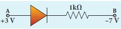
A silicon diode is connected with 1kΩ resistor as shown. Find the value of current flowing through AB is
2.
A optical fibre is made up of a core material with refractive index 1.68 and a cladding material of refractive index 1.44. What is the acceptance angle of the fibre if it is kept in air medium without any cladding?
3.
Why are Infrared radiation referred to as heatwaves? Name the radiations, which are next to these radiation having
(i) shorter λ
(ii) longer λ.
4.
A circular antenna of area 3 m2 is installed at a place in Madurai. The plane of the area of antenna is inclined at 47o with the direction of Earth’s magnetic field. If the magnitude of Earth’s field at that place is 4.1 x 10⁻⁵ T find the magnetic flux linked with the antenna.
5.
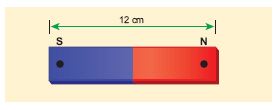
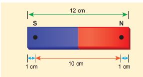
Compute the magnetic length of a uniform bar magnet if the geometrical length of the magnet is 12 cm. Mark the positions of magnetic pole points.
6.
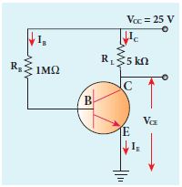
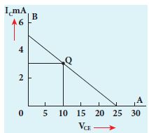
The current gain of a common emitter transistor circuit shown in figure is 120. Draw the DC load line and mark the Q point on it. (VBE to be ignored).
7.
The thickness of a glass slab is 0.25 m. It has a refractive index of 1.5. A ray of light is incident on the surface of the slab at an angle of 60o. Find the lateral displacement of the light when it emerges from the other side of the glass slab.
8.
Compute the torque experienced by a magnetic needle in a uniform magnetic field.
9.
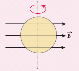
A circular loop of area 5 x 10⁻² m2 rotates in a uniform magnetic field of 0.2T. If the loop rotates about its diameter which is perpendicular to the magnetic field as shown in figure. Find the magnetic flux linked with the loop when its plane is
(i) normal to the field
(ii) inclined 60o to the field and
(iii) parallel to the field.
10.
A ray incident at a point at an angle of incidence of 60o enters a glass sphere of refractive index \(\sqrt{3}\) and is reflected and refracted at the farther surface of the sphere. The angle between the reflected and refracted ray at the surface is _____.
50o
60o
90o
40o
11.
A power of f 11 kW is in transmitted through 220 V. The current through line wire is _________________.
5 A
0.5 A
50 A
500 A
12.
The given electrical network is equivalent to ______.

AND gate
OR gate
NOR gate
NOT gate
13.
If the velocity and wavelength of light in air is Va and λa and that in water is Vw and λw, then the refractive index of water is______.
\(\frac{V_W}{V_a}\)
\(\frac{V_a}{V_W}\)
\(\frac{\lambda_W}{\lambda_a}\)
\(\frac{{V_a}\lambda_a}{{V_W}\lambda_W}\)
14.
The angle of dip at a place, when horizontal and vertical components of earth's field are equal is ______________.
45°
60°
30°
0°
15.
Three wires of equal lengths are bent in the form of loops. One of the loops is circle, another is a semi-circle and the third one is a square. They are placed in a uniform magnetic field and same electric current is passed through them. Which of the following loop configuration will experience greater torque?
Circle
Semi-circle
Square
All of them
16.
A thin semi-circular conducting ring (PQR) of radius r is falling with its plane vertical in a horizontal magnetic field B, as shown in the figure.
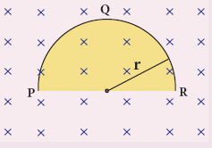
The potential difference developed across the ring when its speed v, is
Zero
\(\frac { { Bv\pi { r }^{ 2 } } }{ 2 } \) and P is at higher potential
πrBv and R is at higher potential
2rBv and R is at higher potential
17.
The electric and the magnetic fields, associated with an electromagnetic wave, propagating along negative X axis can be represented by _____.
\(\vec { E } ={ E }_{ 0 }\hat { i } \) and \(\vec { B } ={ B }_{ 0 }\hat { k } \)
\(\vec { E } ={ E }_{ 0 }\hat { k } \) and \(\vec { B } ={ B }_{ 0 }\hat { j } \)
\(\vec { E } ={ E }_{ 0 }\hat { i } \) and \(\vec { B } ={ B }_{ 0 }\hat { j } \)
\(\vec { E } ={ E }_{ 0 }\hat { j } \) and \(\vec { B } ={ B }_{ 0 }\hat { i } \)
18.
What is dispersion? Obtain the equation for dispersive power of a medium.
19.
Discuss the conversion of galvanometer into an ammeter and also a voltmeter.
1.
The P.D. between A and B is given by
\(V =\left[V_{\mathrm{A}}-V_{\mathrm{B}}\right]-V_{\mathrm{b}}(\mathrm{Si}) \)
\(=[3.3-(-7.4)]-0.7 \)
\(=10.7-0.7=10 \mathrm{~V} \)
The value of current flowing through AB can be obtained by using Ohm’s law
\(I=\frac { V }{ R } =\frac { 10}{ 1\times { 10 }^{ 3 } } ={ 10 }^{ -2 }A=10mA\)
2.
Given, n1 = 1.68, n2 = 1.44, n3 = 1
Acceptance angle, \(\\ { i }_{ a }={ sin }^{ -1 }\left( \sqrt { { n }_{ 1 }^{ 2 }-{ n }_{ 2 }^{ 2 } } \right) \)
\({ i }_{ a }={ sin }^{ -1 }\left( \sqrt { \left( 1.68 \right)^2 -\left( 1.44 \right) ^{ 2 } } \right) ={ sin }^{ -1 }\left( 0.865 \right) \)
\({ i }_{ a }\simeq { 60 }^{ o }\)
If there is no cladding then, n2 = 1
Acceptance angle, \({ i }_{ a }={ sin }^{ -1 }\left( \sqrt { { n }_{ 1 }^{ 2 }-1 } \right) \)
\({ i }_{ a }={ sin }^{ -1 }\left( \sqrt { \left( 1.68 \right) ^{ 2 }-1 } \right) ={ sin }^{ -1 }\left( 1.35 \right) \)
sin−1(more than 1) is not possible. But, this includes the range 0o to 90o. Hence, all the rays entering the core from flat surface will undergo total internal reflection.
Note: If there is no cladding then there is a condition on the refractive index (n1) of the core
\({ i }_{ a }={ sin }^{ -1 }\left( \sqrt { { n }_{ 1 }^{ 2 }-1 } \right) \)
Here, as per mathematical rule,
\(\left( { n }_{ 1 }^{ 2 }-1 \right) \le 1\) or \(\left( { n }_{ 1 }^{ 2 } \right) \le 2\) or \({ n }_{ 1 }\le \sqrt { 2 } \)
Hence, in air (no cladding) the refractive index n1 of the core should be,\({ n }_{ 1 }\le 1.414\)
3.
Infrared radiation waves are produced by hot bodies and molecules so it is referred as heat waves. (eg. Sun)
(i) Electromagnetic waves having shorter λ than Infrared radiation are visible, U - v, X-rays, and ૪ - rays.
(ii) Electromagnetic waves having longer λ than Infrared radiation are microwaves, radiowaves.
4.
B = 4.1 x 10⁻⁵ T; θ = 90o – 47o = 43° ;
A = 3m2
We know that \(\Phi_{B}=B A \cos \theta\)
\(\Phi_{\mathrm{B}}\) = 4.1 x 10–5 x 3 x cos 43o
= 4.1 x 10–5 x 3 x 0.7314
= 89.96 \(\mu \mathrm{Wb}\).
5.
The geometrical length of the bar magnet is 12 cm
Magnetic length = \(\frac { 5 }{ 6 } \times \)(geometrical length)
= \(\frac { 5 }{ 6 } \times \)12 = 10 cm
In this figure, the dot implies the pole points.
6.
β = 120
Base current, \({ I }_{ B }=\frac { 25V }{ 1M\Omega } =\frac { 25 }{ 1\times { 10 }^{ 6 } } =25\mu A\)
We know that
\(\beta =\frac { { I }_{ C } }{ { I }_{ B } } \) (or)
IC = β IB = 120 x 25 μA
= 3000 μA = 3 mA
VCE = VCC - ICRC
= 25 - (3 mA x 5k) = 10 V
7.
Given, thickness of the slab, t = 0.25 m, refractive index, n = 1.5, angle of incidence, i = 60o.
Using Snell’s law, 1 sin i = n sin r
\(sinr=\cfrac { sini }{ n } =\cfrac { sin60^o }{ 1.5 } =0.58\)
\(r={ sin }^{ -1 }(0.58)=35.25^{ 0 }=35^o15'0''\)
Lateral displacement is, \(L=t\left( \cfrac { sin\left( i-r \right) }{ cos\left( r \right) } \right) \)
\(L=\left( 0.25 \right) \times \left( \cfrac { sin\left( 60-35.25 \right) }{ cos\left( 35.25 \right) } \right) =0.1281m\)
The lateral displacement is, L = 12.81 cm
8.
i) Consider a bar magnet of length 2l and pole strength qm
ii) Force experienced by the magnet at each pole is qm B (equal) in opposite direction.
iii) So, magnet experiences a torque.
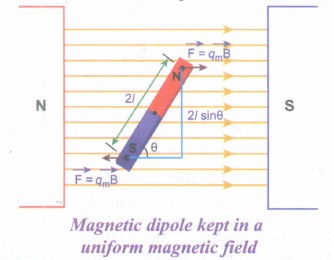
The force experienced by north pole,
\(\vec { { F }_{ N } } ={ q }_{ m }\vec { B } \)
The force experienced by south pole,
\(\vec { { F }_{ S } } =-{ q }_{ m }\vec { B } \)
∴ The net force acting on the dipole is,
\(\vec { F } =\vec { { F }_{ N } } +\vec { F_{ S } } =\vec { 0 } \)
The moment of force or torque experienced by north and south pole about point O is,
\(\vec { \tau } =\vec { ON } \times \vec { { F }_{ N } } +\vec { OS } \times \vec { { F }_{ S } } \)
\(\vec { \tau } =\vec { ON } \times { q }_{ m }\vec { B } +\vec { OS } \times (-{ q }_{ m }\vec { B } )\)
By using right hand cork screw rule, we conclude that the total torque is pointing into the paper. Since the magnitudes \(|\vec { ON } |=|\vec { OS } |=l\) and \(|{ q }_{ m }\vec { B } |=|-{ q }_{ m }\vec { B } |\).
The magnitudes of total torque about point O is
ፒ = l x qmB sinθ + l x qmB sinθ
ፒ = 2l x qmB sinθ
ፒ = pmB sinθ (∴ qm x 2l = pm)
In vector notation, \(\vec { \tau } =\vec { { p }_{ m } } \times \vec { B } \).
9.
A = 5 x 10⁻² m2; B = 0.2 T
(i) θ = 0°;
\({ \Phi }_{ B }=BAcos\theta =0.2\times 5\times { 10 }^{ -2 }\times { cos }0^{ o }\)
\({ \Phi }_{ B }=1\times { 10 }^{ -2 }Wb\)
(ii) θ = 90° – 60° = 30°;
\(\Phi_B\) = BAcosθ = 0.2 x 5 x 10-2 x cos 30o
\({ \Phi }_{ B }=1\times { 10 }^{ -2 }\times \frac { \sqrt { 3 } }{ 2 } =8.66\times { 10 }^{ -3 }Wb\)
(iii) θ = 90°;
\({ \Phi }_{ B }\) = BA cos90o = 0
10.
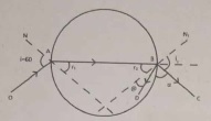
\( \mathrm{i}=60^{\circ} \)
\( \mathrm{n}=\sqrt{3}\)
Applying Snell's law at A
\(\frac{\sin i}{\sin r_1}=\sqrt{3}\)
\(\sin \mathrm{r}_{\mathrm{t}}=\frac{\sin 60}{\sqrt{3}}=\frac{\sqrt{3}}{2} \cdot \frac{1}{\sqrt{3}}=\frac{1}{2}\)
r1 = 30°
If r1 = 30° & r2 = 30°
Applying Snell's law at 'B'
\(\frac{\sin r_2}{\sin i_2}=\frac{1}{\sqrt{3}}\)
\(\sin i_2 =\sqrt{3} \times \sin 30^{\circ} \)
\(=\sqrt{3} \times \frac{1}{2} \)
\( \sin i_2 =\frac{\sqrt{3}}{2}=\sin 60^{\circ} \)
\( i_2 =60^{\circ} \)
At B,
\( \mathrm{r}_2=30^{\circ} \text { also } \theta =30^{\circ} \)
\(\therefore \theta+\alpha+\mathrm{i}_2 =180^{\circ}\)
\(\alpha =180^{\circ}-\left(\mathrm{i}_2+\theta\right) \)
\( =180^{\circ}-\left(60^{\circ}+30^{\circ}\right) \)
\( =180^{\circ}-90^{\circ} \)
\(\alpha =90^{\circ} \)
11.
\(l=\frac{P}{V}=\frac{11000}{220}=50 \mathrm{~A}\)
12.
\(Y_1=\overline{A+B}, y_2=\overline{A+B}=A+B, y=\overline{A+B}\)
13.
Refractive index of water \(=\frac{Velocity \ of \ light \ in \ air(V_s)}{Velocity \ of \ light \ in \ water(V_w)}\)
14.
(a)
45°
15.
(a)
Circle
16.
(d)
2rBv and R is at higher potential
17.
\( { E } ={ E }_{ 0 }\hat { k } \) and \({ B } ={ B }_{ 0 }\hat { j } \)
18.
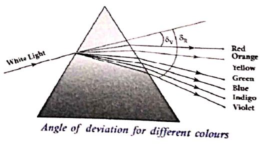
Dispersion: It is splitting of white light into its constituent colours.
(i) Consider a beam of white light passes through a prism; it gets dispersed into its constituent colours as shown in Figure.
(ii) Let \(\delta_{v}, \delta_{R} \) are the angles of deviation for violet and red light. Let nV and nR are the refractive indices for the violet and red light respectively
(iii) The refractive index of the material of a prism is given by the equation
\(\mathrm{n}=\frac{\sin \left(\frac{\mathrm{A}+\mathrm{D}}{2}\right)}{\sin (\mathrm{A} / 2)}\)
(iv) Here A is the angle of the prism and D is the angle of minimum deviation. If the angle of prism is small of the order of 10o, the prism is said to be a small angle prism.
(v) When rays of light pass through such prisms, the angle of deviation also becomes small. If A be the angle of a smitt angle prism and the angle of deviation then the prism formula becomes.
\(n=\frac{\sin \left(\frac{A+\delta}{2}\right)}{\sin (A / 2)}\)
For small angles of \(A\ and \ \delta \)
\(\sin \frac{A+\delta}{A} \approx \frac{A+\delta}{A} \)
\(\sin \frac{A}{2} \approx \frac{A}{2} \)
\(n=\frac{(A+\delta / 2)}{(A / 2)}=\frac{A+\delta}{A}=1+\frac{\delta}{A} \)
Further simplifying,
\(\frac{\delta}{A} =n-1 \)
\(\delta =(n-1) A \) .....(1)
(vi) When white light enters the prism, the deviation is different for different colours. Thus, the refractive index is also different for different colours
For Violet colour, \( \delta_{\mathrm{v}}=\left(\mathrm{n}_{\mathrm{v}}-1\right) \mathrm{A} \) ...(2)
For Red colour, \(\delta_{\mathrm{R}}=\left(\mathrm{n}_{\mathrm{R}}-1\right) \mathrm{A} \) ....(3)
(vii) As, angle of deviation for violet colour \(\delta_{v}\) is greater the angle of deviation for red colour \(\delta_{\mathrm{R}}\) the refractive index for violet colour nv is greater than the refractive index for red colour nR Subtracting \(\delta_{v}\) from \(\delta_{\mathrm{R}}\) we get
\(\delta_{\mathrm{v}}-\delta_{\mathrm{R}}=\left(\mathrm{n}_{\mathrm{v}}-\mathrm{n}_{\mathrm{R}}\right) \mathrm{A}\) ....(4)
(viii) The term \(\left(\delta_{v}-\delta_{R}\right)\) is the angular separation between the two extreme colours (violet and red) in the spectrum is called the angular dispersion. If we take \(\delta\) is the angle of deviation for any middly ray (green or yellow) and the corresponding refractive index. Then,
\(\delta=(n-1) A\) .....(5)
Dispersive power (ω):
It is the ability of the material of the prism to cause dispersion. It is defined as the ratio of the angular dispersion for the extreme colours to the deviation for any mean colour.
Dispersive power
\(\omega=\frac{\text { Angular dispersion }}{\text { Mean deviation }}=\frac{\delta_{v}-\delta_{R}}{\delta}\) ....(6)
Substituting \(\left(\delta_{\mathrm{v}}-\delta_{\mathrm{R}}\right) \text { and }(\delta) \)
\(\omega=\frac{\mathrm{n}_{\mathrm{v}}-\mathrm{n}_{\mathrm{R}}}{(\mathrm{n}-1)} \) .......(7)
(ix) Dispersive power is a dimensionless quality It has no unit. Dispersive power is always positive. The dispersive power of a prism depends only on the nature of material of the prism and it is independent of the angle of the prism.
19.
(i) Galvanometer to an Ammeter:
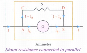
(i) Ammeter is an instrument used to measure current flowing in the electrical circuit.
(ii) The Ammeter must offer low resistance such that it will not change the current passing through it. So, ammeter is connected in series to measure the circuit current.
(iii) A galvanometer is converted into an ammeter by connecting a low resistance in parallel with the galvanometer.
(iv) Let I be the current passing through the circuit. When current I reaches the junction A, it divides into two components.
a) Ig → Current passing through the galvanometer
b) I - Ig → Current passing through the shunt resistance.
(v) The potential difference across the galvanometer is same as the potential difference across the shunt resistance.
\(\mathrm{V}_{\text {galvanometer }} =\mathrm{V}_{\text {shunt }} \)
\(\Rightarrow \mathrm{I}_{\mathrm{g}} \mathrm{R}_{\mathrm{g}} =\left(\mathrm{I}-\mathrm{I}_{g}\right) \mathrm{S} \)
\(\mathrm{S} =\frac{I_{g}}{\left(I-I_{g}\right)} R_{g} \) (or)
\(\mathrm{I}_{\mathrm{g}}=\frac{S}{S+R_{g}} I \Rightarrow I_{g} \propto I\)
Since, the deflection in the galvanometer is proportional to the current passing through it.
\(\theta=\frac{1}{G} I_{g} \Rightarrow \theta \propto I_{g} \Rightarrow \theta \propto I\)
Where, Rg → Galvanometer resistance, S → Shunt resistance.
Since shunt resistance is connected in parallel to galvanometer,
Effective resistance,\(\frac{1}{R_{e f f}}=\frac{1}{R_{g}}+\frac{1}{S} \Rightarrow R_{e f f}=\frac{R_{g} S}{R_{g}+S}=R_{a}\)
Ra ⇒ low resistance. An ideal ammeter has zero resistance.
The percentage error in measuring a current through an ammeter is,
\(\frac{\Delta I}{I} \times 100 \%=\frac{I_{i d e a l}-I_{a c t u a l}}{I_{a c t u a l}} \times 100 \%\)
(ii) Galvanometer to a voltmeter:
i) A voltmeter is an instrument used to measure potential difference across any two points in the electrical circuits.
ii) Voltmeter must have high resistance and when it is connected in parallel, it will rot draw appreciable current so that it will indicate the true potential difference.
iii) A galvanometer is converted into a voltmeter by connecting high resistance Rh in series with galvanometer.
iv) Let Rg be the resistance of galvanometer and Ig be the current with which the galvanometer produces full scale deflection.
v) Since the galvanometer is connected in series with high resistance, the current in the electrical circuit is same as the current passing through the galvanometer.
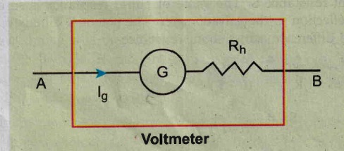
\(\mathrm{I}=\mathrm{I}_{\mathrm{g}} \)
\(\mathrm{I}=I_{g} \Rightarrow I_{g}=\frac{\text { potential difference }}{\text { total resistance }} \)
Since the galvanometer and high resistance are connected in series, the voltmeter resistance is,
\(R_{v} =R_{g}+R_{h} \)
Therefore,
\(I_{g} =\frac{V}{R_{g}+R_{h}} \)
\(\Rightarrow R_{h} =\frac{V}{I_{g}}-R_{g} \)
Note that \(I_{g} \propto V\)
Rh is very large. An ideal voltmeter has infinite resistance

12th Standard Syllabus & Materials
12th Standard
TN 12th Computer Applications களப்பெயர் முறைமை (DNS) Sample Question Papers Study Material - QB365 Set A
NEW12th Standard
TN 12th Computer Applications வலையமைப்பு எடுத்துக்காட்டுகள் மற்றும் நெறிமுறைகள் Sample Question Papers Study Material - QB365 Set A
NEW12th Standard
TN 12th Computer Applications கணினி வலையமைப்பு ஓர் அறிமுகம் Sample Question Papers Study Material - QB365 Set A
NEW12th Standard
TN 12th Computer Applications PHP-உடன் MySQL-ஐ இணைத்தல் Sample Question Papers Study Material - QB365 Set A



Tamilnadu Stateboard 12th Standard Subjects

Maths

Chemistry
Physics

Biology

Computer Science

Business Maths and Statistics

Economics

Commerce

Accountancy

History

Computer Applications
Biology
Computer Technology
Computer Applications
Computer Science
Business Maths and Statistics
Commerce
Economics
Maths
Chemistry
Physics
Computer Technology
History
Accountancy

Tamil

English

French
Tamilnadu Stateboard Standards


